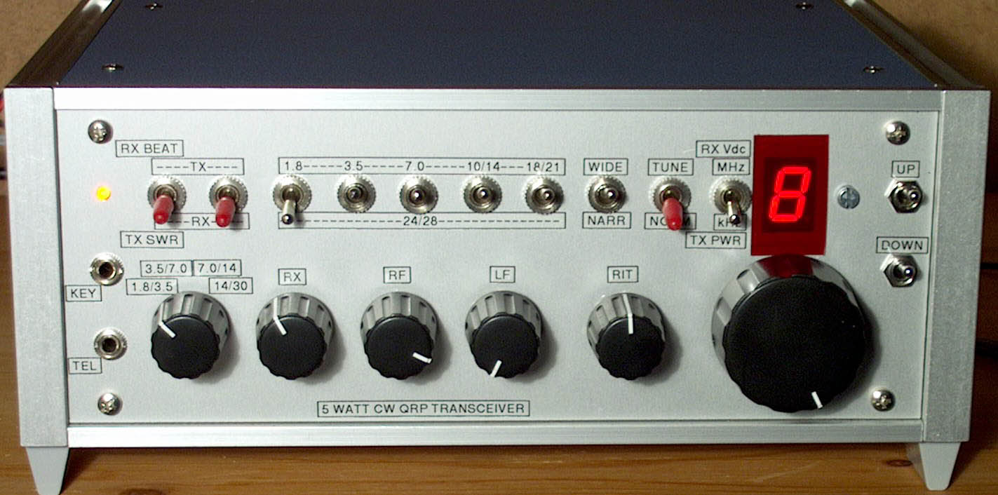
"MY TRX"
All band CW transceiver 5 watt QRP
plus general coverage reception.
(2001)
KLIK HIER VOOR DE NEDERLANDSE VERSIE
Ready for QRP work
Contact with the world
The design
In principle it is a VFO from 28 to 60 MHz with a special frequency stabilizer and a frequency
divider (/2; /4; /8; /16) to generate the working frequency. This signal is amplified to
5 watt and is also used for the Direct Conversion receiver.
Block diagram
Block diagram.
big diagram
Working principle
(See the block diagram)
A VCO with a frequency range from 28 to 60 MHz is followed by a frequency divider to obtain
the working frequency. The division ratio is /16; /8; /4/; /2 for the ranges 1.8-3.5 MHz;
3.5-7.0 MHz; 7.0-14.0 MHz and 14.0-30.0 MHz
Harmonics of the VCO frequency divided by 4096 are locked to a VXO. If locking occurs, there is
a small frequency range of approx. 15 to 262 kHz (depending on the frequency band, 15 kHz for 160 m,
262 kHz for 10 m), tuneable by the 10 turn potmeter of the VXO.
By pressing the up/down switches, it is possible to go to the nearest next small frequency range that
is tuneable by the VXO.
For large frequency changes, there is a switch so that you can tune the VCO close to the
desired frequency with the 10 turn potentiometer.
Frequency locking principle
The VCO frequency is divided by 4096, giving a frequency range from 6835 to 14648 Hz.
This frequency is used to control the sample & hold circuit. The input of that circuit is the VXO.
The output of the sample & hold controls the VCO. A frequency lock will occur if:
N x (6835 to 14648 Hz) = VXO frequency(3671 to 3703 kHz)
That means that for each integer value for N between 250 and 541 there is a frequency lock.
When there is a lock, the frequency variation of the VCO is:
4096/N x (3671 to 3703 kHz) with N between 250 and 541.
At low frequencies, the frequency variation is less than at high frequencies.
At 1.8 MHz the frequency variation is half of that at 3.6 MHz, at 3.68 MHz it is exactly the
same as the variation of the VXO and at 7.36 MHz it is twice the VXO variation.
Frequency change
There are two methods implemented to change to other harmonic locks (other values of N between
252 and 541):
VFO diagram
Circuit diagram of the VFO, modified circuit in October 2002 for better reproducibility.
big diagram
The RIT
The RIT is not linear. The RIT frequency depends on the VXO frequency. Tune to zero beat with
the RIT at centre position (or S2 off) when receiving, then turn the RIT potentiometer to the
left or right to obtain the desired audio frequency of the received CW signal.
For the higher bands the frequency variation of the RIT control is bigger. The resistors
around the RIT potentiometer are selected for less RIT frequency variation near the centre
position of the RIT potentiometer.
The RIT switch S2 is toggled together with the TX/RX switch S3.
The Sample & Hold circuit
There are two sample & hold circuits. One with a small capacitor for fast sampling and a second
one with a bigger capacitor for slow sampling of the output of the first sample & hold.
This second one does not discharge between two sampling moments, due to the bigger capacitor.
The Control Loop
Two potentiometers are used to control the stability. The 100 ohm potentiometer in series with
the 100 uF capacitor is adjusted for stability at the lowest VCO frequency (VCO at 28 MHz).
The 10k ohm potentiometer is set to the centre between the two "just locking" positions.
If it is not possible to get the VCO locked, increase the 100 uF capacitor and/or the 22k
resistor of the loop filter. If the up/down switches do not work correctly, increase Rvxo. All
cables from the control loop circuit to the switches and tuning potentiometers are screened.
Adjustment of the loop potentiometer can be done with an oscilloscope at TP2. A very simple and
perhaps even better method is to tune to a strong carrier just above 14 MHz and adjust the 100 ohm
potentiometer so that you will hear the cleanest distortion free audio tone.
Direct Conversion Receiver diagram

Circuit diagram of the direct conversion receiver
big diagram
If you want to read details about mixer and RF amplifier, go via the home page index to the 4 band VXO tuned QRP transceiver.
Transmitter diagram
Circuit diagram of the transmitter
big diagram
Frequency counter and swr bridge diagram

Circuit diagram of the optional frequency counter and swr bridge
big diagram
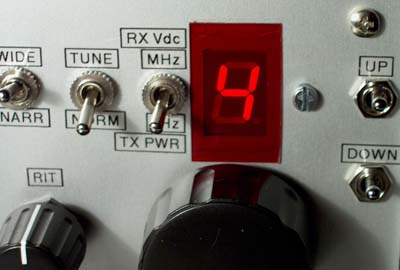
The frequency counter with one 7 segment LED display
Notes
The VXO and VCO are placed together in a screened enclosure. The frequency counter is also screened.
Built via the ugly method (dead bug method). Parts are soldered at both sides of he double
sided unetched print.
Inductances are commercially available types looking like big resistors.
Do not use a HCT type but a HC type!
Performance
Sensitivity: 0.15 to 0.3 uV signals are readable
AM dynamic range: 85 to 100 dB (good)
RX current: 90 mA
Transmit power (12 Vdc):
- QRO: 7 to 9 W for the bands 1.8 to 24 MHz, 4.5 W at 28 MHz.
- QRP: 2.5 to 3 W for the bands 1.8 to 24 MHz, 2 W at 28 MHz.
Suppression of spurious emission: below 30 MHz: 43 dB, above 30 MHz: 55 dB
SOFTWARE FOR THE FREQUENCY COUNTER
"FREQTRX1.ZIP" WITH "FREQTRX1.ASM" TO PROGRAM THE FREQUENCY COUNTER
PHOTOGRAPHS
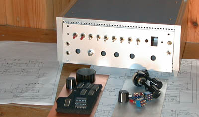
The Birth of the "MY TRX" Transceiver.
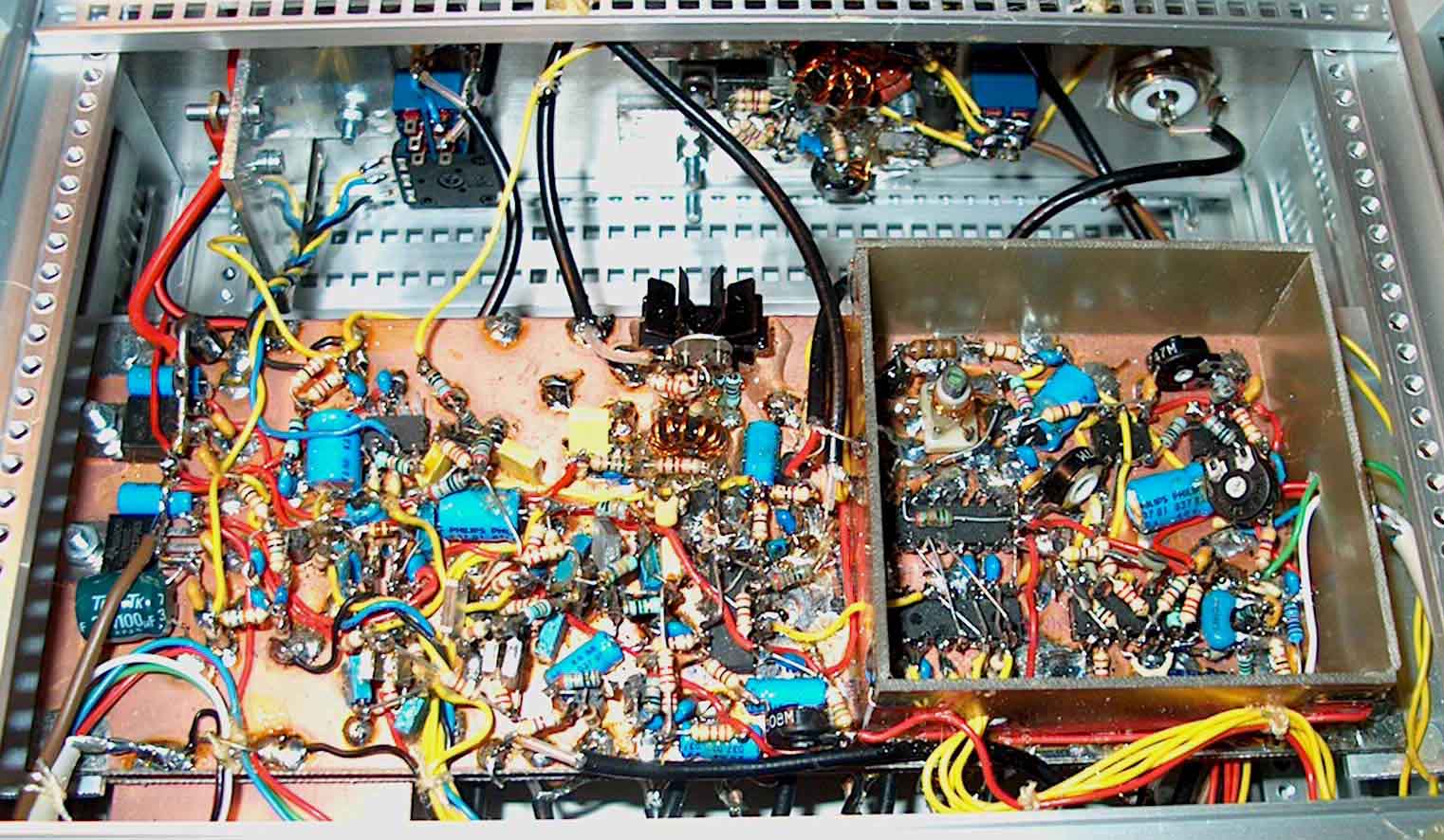
The VFO, Direct Conversion RX and PA driver
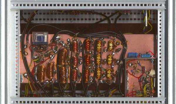
The SWR bridge, Lo-pass filters and Frequency counter
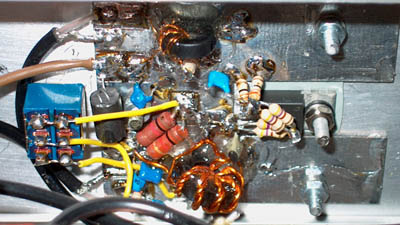
The Final amplifier with 2SC1969 transistor and QRO - QRP switch
(at the back side of the transceiver)
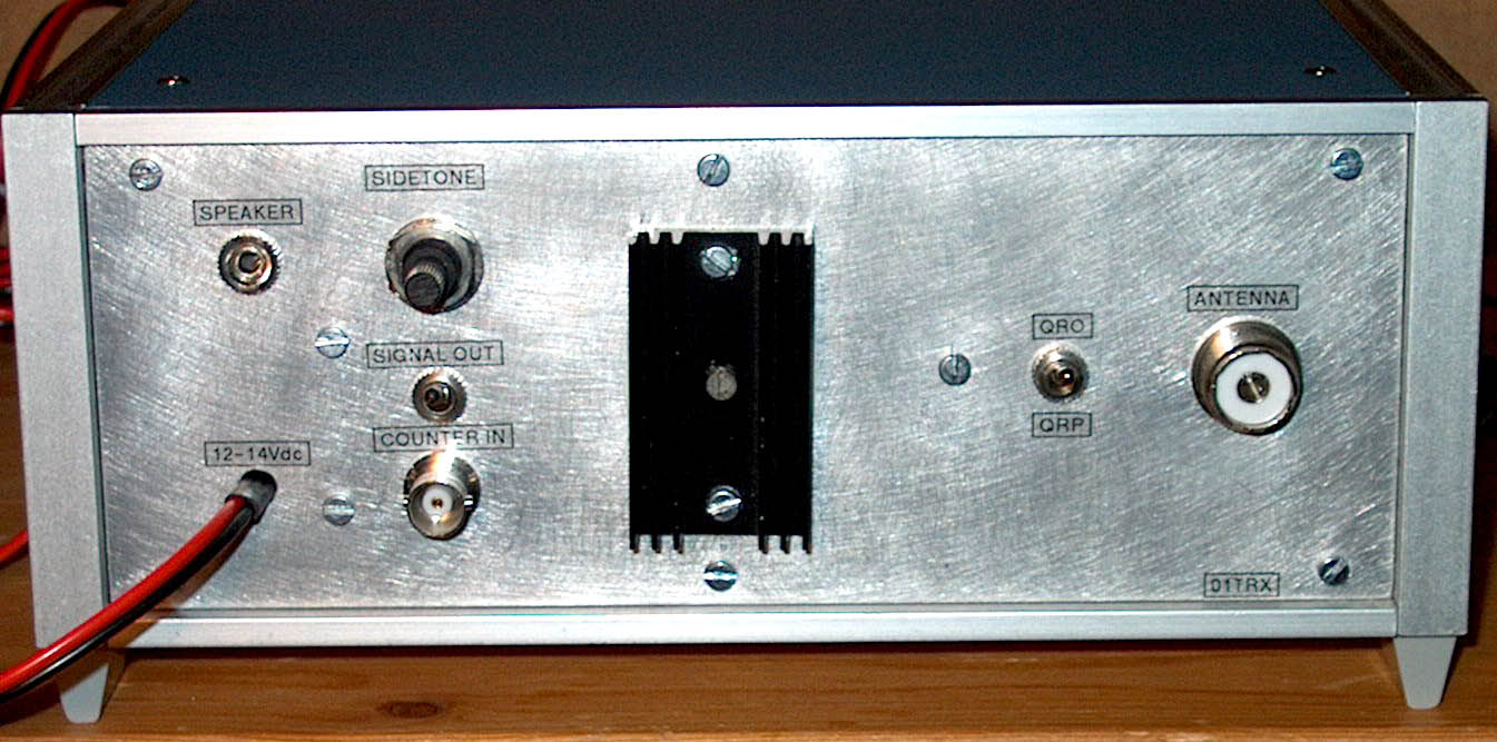
Back side of the transceiver