The rather ancient Icom IC202 is an ideal rig for portable SSB/CW on the 2 m band, and also using it as a tunable IF with transverters on to other bands. The IC202 uses a crystal VXO and multiplier mixed with a fixed 9 MHz crystal filter in it's IF to give an output frequency in the 144 MHz amateur band.
One of the main reasons I like the IC202 is that it produces a very clean output signal, and there are non of the problems associated with synthesized rigs like the Yaesu FT290, with their noisy oscillators. I have found that the synthesizer products show up even more on low power as it would be when used in conjunction with a transverter. I use the 202S as an IF for my 23 cm transverter.
The one drawback of the IC202 is the rather crude analogue frequency display.
So when a very good friend of mine (David G4DHF) came up with a layout for a compact digital display I offered to make the printed circuit boards and put the display into the 202, the results of which you can see below.
Anyone how has seen the IC202 will know that it is quite a small rig so to fit anything inside the case is quite a task. The following pictures show some of the details of the modifications made to the IC202.
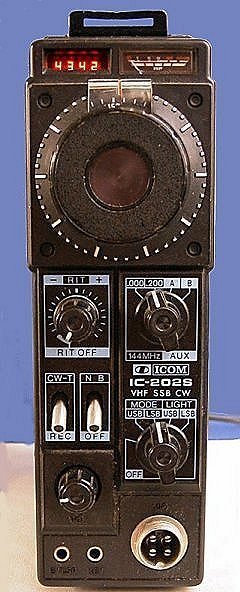
The front of the IC202 showing the four digit display.
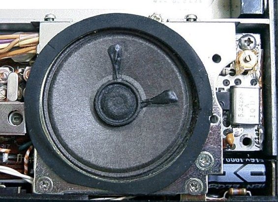
The frequency counter boards mounted under the speaker.
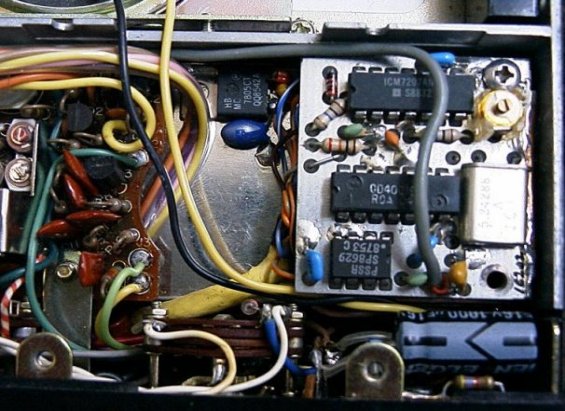
The top board of the frequency counter.
One of the hardest jobs was the installation of the digital display. Here a small 4 digit seven segment LED display is used. It's the size of a 14 PIN IC, in the picture below you can see it has bubble lenses over each digit to magnify the characters.
 The front panel and front chassis had to be
removed to allow access to the only space available on the front panel. This is
in the area where the original 'power on' led was mounted. The plastic panel had
to be cut carefully to allow the display to show. Screened wires run from the
display LED's to the main counter boards, you can just see the large yellow wire
on the picture above.
The front panel and front chassis had to be
removed to allow access to the only space available on the front panel. This is
in the area where the original 'power on' led was mounted. The plastic panel had
to be cut carefully to allow the display to show. Screened wires run from the
display LED's to the main counter boards, you can just see the large yellow wire
on the picture above.
The counter measures the output of the VXO which is corrected to read the frequency at 144 MHz as the counter chip used, an Intersil ICM7217, has a programmable offset for the 9 MHz IF of the IC202. The display is set up to read 1 kHz . So 144.350 MHz would show as 4350 on the display. With a bit of interpretation of the last digit it is possible to get within 500 Hz which is a whole lot better than the 10 kHz readings available on the analogue display. (The last digit is allowed to dither, so it is possible to see if it is counting low or high.)
The display may not be up to that of modern rigs but is does work OK on the bands and it is possible to QSY or set up on a sked frequency with reasonable accuracy. And unlike the analogue display there is no problem with tracking from one end of the VXO range to the other.
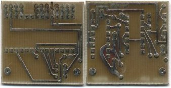
Above are the two frequency counter PCB's. They are stacked one above the other when installed in the rig. The board on the right has the crystal oscillator and prescaler input IC circuits, and is the top board shown in the pictures of the IC202, the other board houses the main 28 pin counter IC chip.
This Page is ©
![]() 2000
2000