G6UYJ PIC Frequency Counter
Mark 1
This project originally started off about 5 years ago when I built a frequency counter from a web article by the Perth Electronics Group. Sadly this article is no longer on the Internet. It used a PIC16C57 as the microcontroller and 74HC4040s as the counters. The information from the counters was clocked into a parallel to serial buffer and then moved into the PIC. The counter worked very well, however, when placed next to my IC202 it produced so much noise that the IC202 was not usable.
Mark 2
The Mark 2 version of the counter started about a year ago. There is nothing too special about it compared to many of the designs on the web. The information is put here to help others that are developing their own frequency counters.
The incoming signal is connected to one of two prescalers. For low frequencies (<70MHz) the signal is amplified with an MSA0685 buffer and then fed into a linearly biased 74AC04 gate. This gives a square wave out that can be fed to the counter. For inputs up to 150MHz an additional divide by 4, made from a 74AC74, is used before the waveform gets to the counter. For high frequency signals (up to 3GHz) the signal is buffer this time with a MSA0340 and then fed to a MC12034 prescaler. The signal is either divided by 32 or 64. This is again fed into a 74AC04 gate, this time biased at mid rail and then onto the counter.
I wanted to get the most out of the digital logic. In the mark 1 counter the 74HC4040 dividers worked to over 75MHz. Most of the counters documented on the web seem to go to around 40MHz because of the 8 bit divided used before the PIC. By using the 12 bit 74HC4040 it gives an extra 4 bits in the counter that allows the 40MHz barrier to be broken. The three different outputs from the prescalers are selected by the a 74HC153 and fed to the divider chain. At the end of every count interval the PIC takes the information, processes it and sends it to a 2x16 LCD display.
Frequency counter features:
- 3 gate times 1sec, 0.5sec, 0.25sec
- 4 input modes 70MHz, 150MHz, 2GHz, 3GHz
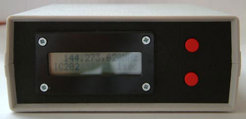
- Extra modes IC202, takes 134MHz output from IC202 oscillator and displays TX/RX frequency
Circuit Diagrams and Software
The circuit is split into the prescalers and the counter itself. The source code for the counter is written in assembly. Its not pretty but it works for me!
I drew the circuit diagrams up after I built the unit so I can't guarantee that all the component value are correct.
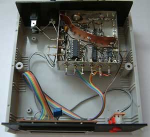
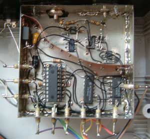
Construction
The unit is built in a tin plate box in the dead bug style of construction. Again its not pretty but it works well for a one off project. Ive tried to keep all the noise inside the box so there are feedthrough caps on all the lines and a copper shield between the digital and RF sections. The 4.096MHz OCXO is on the other side of the board.
Just a quick disclaimer, if you fry something even if my design is wrong it is your problem! I have tried to make these details as accurate as possible but I accept no responsibility for any errors or omissions. There is no technical support for any of my projects.