Ground gain and radiation angle at VHF
Do you want an extra 5-6 dB gain? Do you want your radiation at an angle hitting the moon for eme? You may loose 10-20 dB at some angles and gain 5-6 dB at others due to ground gain.
Ground gain is available at VHF for low angle radiation and horizontal polarized antennas at heights of app. 1-5 wavelengths. Ground gain can be 5-6 dB from flat ground and can be estimated using simple formula or monograms. For non-flat ground the ground gain can be calculated with reasonable accuracy by software designed for amateur radio use at HF.
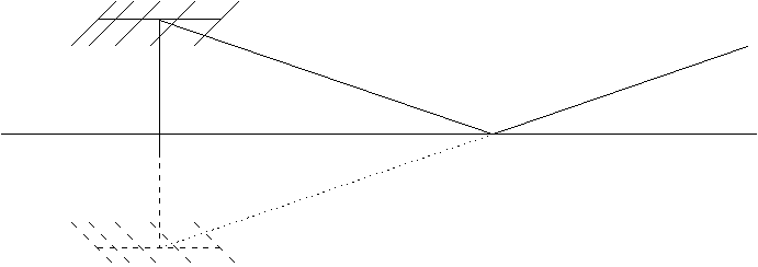
Ground gain occurs at the radiation angles where the received or transmitted signal and the signal from the ground image of the antenna are in phase. You can imagine your antenna is in front of a large reflector (dish) where you should place the antenna at the focus point to get most gain. Ground reflections apply to all frequencies, but this paper concentrates on the effects at 50 and 144 MHz.
Contents:
1 Foreword
*2 Radiation angle, ground reflection and ground gain
*2.1 Flat Ground
*2.2 Ground reflection point and 1. Fresnel zone
*2.3 Sloping ground
*2.4 Refraction and curved earth
*3 Modeling radiation angles by computers
*4 Stacking, BLU switching and BIP/BOP phasing
*5 Polarization and ground effects
*6 Conclusions
*7 Acknowledgments
*8 Literature
*
Target group:
Eme’rs who want some theory on ground gain and radiation angle at 50 and 144 MHz and VHF amateurs who want to direct their radiation at some preferred radiation angle for a specific propagation mode (MS, Aurora, Es…).
Objectives:
After the lesson you should:
- know how to get 5-6 dB ground gain for eme
- know why radiation angle may differ from the elevation angle of the boom
This lecture will be held in English but questions may be put in German and French (QRS s.v.p.).
Lecture by OZ1RH, operator at OZ9EDR/OZ5W contest team
At the Weinheim UKW-Tagung 1995 I gave a lecture on Troposcatter at 50 MHz – 700km QSO’s anytime. This lecture included something on ground gain and radiation angles. Now I want to share my findings on this with specific attention on its relevance for eme on 50 and 144 MHz.
To make my lectures more lively I do them without a fully written text and I base my speech only on my prepared overheads. Actually I have a PowerPoint presentation ready for you, so if the hardware will work you will experience some online simulations of ground gain. If you ask some interesting questions I will be happy to answer, and this will make the lecture even more interesting for you. My lecture may thus include other ideas than presented here, and you can't be sure it will include all of the following. So my best advise to you is to read the text and come to the lecture with some good questions.
My call is most likely unfamiliar to you. I was licensed in 1963 and qualified half a year before being 18 for my extra class license. I worked mostly HF and hold DXCC. I have done some 144 MHz contesting since the late sixties and for the last few years I have been in OZ9EDR/OZ5W contest team. I have no education in electronics, but hold bachelor degrees from the Copenhagen Business School of Commerce in public administration and organization, strategy and planning. I am employed in the computer business, so this text is based only on my leisure time study of the referenced literature and on my experience from the bands. I know my words are not the whole truth, but I hope they come closer to "nothing but the truth".
I admit my eme experience is very limited. Some years ago I have heard a few stations on 144 MHz including KB8RQ so strong I thought he was a local. He had very deep QSB and today I know ground reflections may give deep QSB. On 50 MHz the eme signal of OZ5W has been seen with FFTDSP by W7GJ and I heard fractions of him just at the time where I had calculated we both had ground gain.
In the sixties I was active on HF and I learned a little on radiation angles at HF. In the beginning of the nineties I started being active on VHF from OZ9EDR/OZ5W and I wondered if ground reflection and radiation angles applies to VHF. I found it does indeed, and now I want to share this knowledge with you.
Much of the literature I have read dates back to 1954-60, where propagation around 50 MHz was a hot item among scientists and radio engineers. They knew about radiation angles and ground gain.
Limitations of the subject:
Ground reflections applies to all frequencies, but here I concentrate on the effects at 50 and 144 MHz. On the higher bands your antenna will be many wavelength up and ground reflections does not play a significant role. Above 432 MHz sky noise temperature is lower than ground noise temperature so illuminating the ground with your beam pattern to get ground gain will increase noise in your RX.
The first chapters are based on horizontal polarization unless specifically noticed. Vertical and circular polarization is mentioned in the later chapter on polarization and ground effects.
The radiation angles are the angles where the transmitted signal and the signal from the ground image of the antenna are in phase. You can imagine your antenna is in front of a large reflector (dish) where you could place the antenna at the focus point to get most gain. This gain is typically 5-6 dB but dependent on the shape of the ground in front of the antenna and the antenna height.

The following radiation angles can be calculated for a QTH on a flat ground:
|
Beam height over flat ground in meters |
432 MHz |
144 MHz |
50 MHz |
|
10 m |
1 º |
3 º |
9 º |
|
20 m |
0,5 º |
1,5º |
4 º |
A horizontal polarized antenna being many wavelengths up will have a radiation pattern with many loops in the vertical plane:
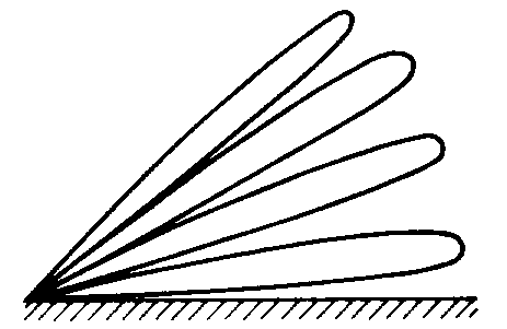
Horizontal dipole many l up

Horizontal beam many l up
In order to get the vertical pattern of a beam over ground, one should multiply the pattern of a dipole over ground with the free space pattern of the beam. At angles where the dipole gives zero radiation the beam will also have zero radiation (in practice "only" -10 to -20 dB with average ground). Good ground conductivity produces deeper minima.
|
|
|
|
2 WL up |
3 WL up |
|
|
5 WL up |
|
|
A 2M18XXX has app. 15,3 dBd free space gain or 17,5 dBi. If this approximate value is subtracted from the gain values calculated by Terrain Analyzer we get an estimate of the ground gain. The following data can be taken from the curves:
|
Antenna height over flat ground |
App. ground gain in dB |
Maximum radiation at degrees |
|
½ l |
-1,7 |
13 |
|
1 l |
2,6 |
11 |
|
2 l |
4,8 |
7 |
|
3 l |
5,3 |
4,5 |
|
4 l |
5,4 |
3,75 |
|
5 l |
5,5 |
3 |
|
10 l |
5,2 |
1,5 |
I have shown the figures as read from the plots, but remember that the calculations are not accurate to neither a fraction of a dB nor a fraction of a degree. Take the values only as a tendency.
It is seen that the antenna needs to clear the ground by at least 2 l to get about 5 dB ground gain over flat ground and the ground gain will be at in the range of 7-1 degree.
The plots also show that the higher up the antenna gets the power will be split into more and thinner loops, and the higher loops have little less gain than the lowest loop.
Let us examine the basic geometry and formulas involved if the ground is flat.
Radio waves between two points mostly propagate within a so-called 1. Fresnel zone, which may be imagined as a cigar formed tube. The loop in the vertical radiation pattern of a horizontal beam over reflecting ground is formed by phase interference between the direct and the wave reflected on the ground. The ground doing the reflection is mostly the ground within the 1. Fresnel zone between the distant station and the ground image of your antenna. The geometry is shown on the following figure taken from "The scatter propagation Issue": Proc. of the IRE, October 1955, p. 1228:
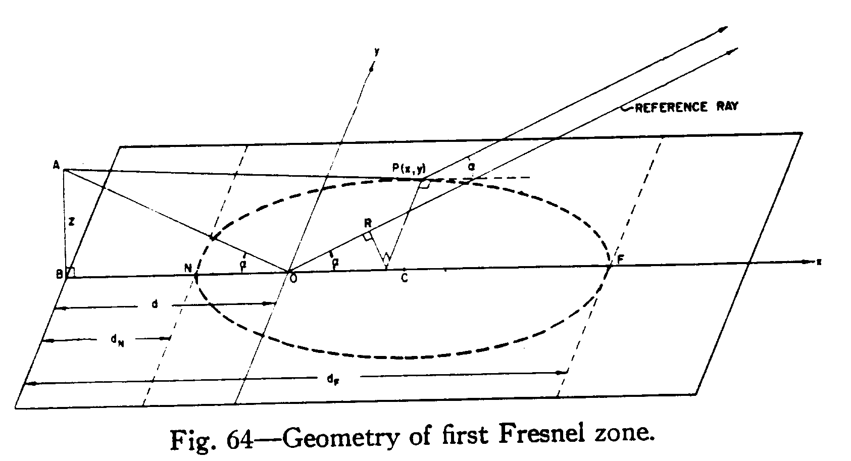
|
Antenna height : l z = ——— 4 sin a |
Distance to reflection point : z d = ——— tan a |
|
Distance to near edge of first Fresnel zone: 2 Ö 2 dN = d ( 3 - ———)cos a |
Distance to far edge of first Fresnel zone: 2Ö 2 dF = d (3 + ———)cos a |
|
Maximum width of the zone: w = 4 Ö 2 z |
The ground within this 1. Fresnel zone should be able to reflect VHF. If it is covered with houses (suburban area) or has many small irregularities (rocks) you get little reflection and ground gain. If you are in a suburban area you may have noticed your neighbors within the 1. Fresnel zone often gives you a call (if their phone works!) complaining about TVI and you probably have noticed you can hear many computers and other noise sources from this area. So even if you could have ground gain for transmitting the noise sources may mask reception from the low moon angles, thus you have little use of ground gain from such a QTH.
I have found some curves, which may help you to estimate radiation angles and ground reflections at 50 MHz for flat ground:
|
|
|
IRE Transactions on Communication Systems, March 1960, p. 14-19
Most amateurs do not live with perfect flat reflecting ground around them, thus it is important to know what happens to the radiation angle when the ground is not flat. I hope your ground is sloping down, if not you are in a hole which makes low angle radiation with ground gain difficult. No ground gain will let you radiate though mountains for eme…
If the reflecting ground is sloping down low radiation angles are possible without a high tower and you may even get a vertical radiation pattern without loops. The downward slope of the hill subtracts something from the radiation angle compared with flat ground.
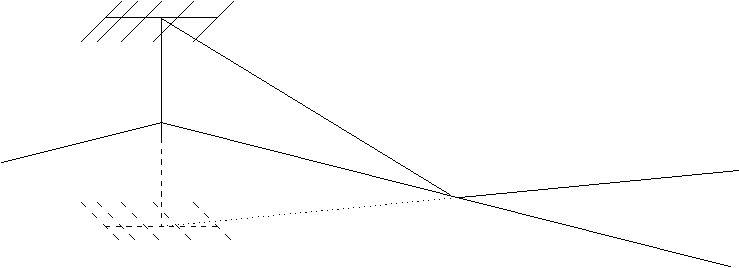
If you have a hill with a long enough slope of 20º your antenna needs only to be ½ l up and it will illuminate all radiation angles from less than 1º to 10º. If you put your antenna up higher at this QTH, you may get loops and consequently also some minima in the vertical radiation pattern. Hilltop QTH’s are complicated regarding radiation angles and computer calculations are needed to get just an estimate.
In order to get ground gain your antenna must illuminate the ground. If you have sloping ground this could mean your antenna should aim down along the slope, that is have negative elevation in order to get maximum ground gain.
30 years ago I had a student job recording weather pictures from low orbiting ESSA/Nimbus satellites. We used 4x10 elm at 136 MHz about two wavelengths up. The automatic tracking system, as I recall, measured the phase difference of the 4 beams in order to adjust for max signal. Sometimes it locked to the ground-reflected wave and tried to force the antenna booms to negative elevation angles. At that time I was told this was an error, but today I think the ground reflected signal was stronger than the direct one at low angles.
For very low radiation angles refraction in the atmosphere should also be taken into account. Refraction is the effect of the diminishing refractivity of the atmosphere with increasing height (air gets thinner and lees humidity higher up) causing the radio wave to be bent (refracted) towards the earth. This refraction is also known as 4/3 R, meaning that to radio waves the earth looks flatter, as if its radius were 4/3 of its actual radius. Diffraction around the round earth has a minor but similar effect.
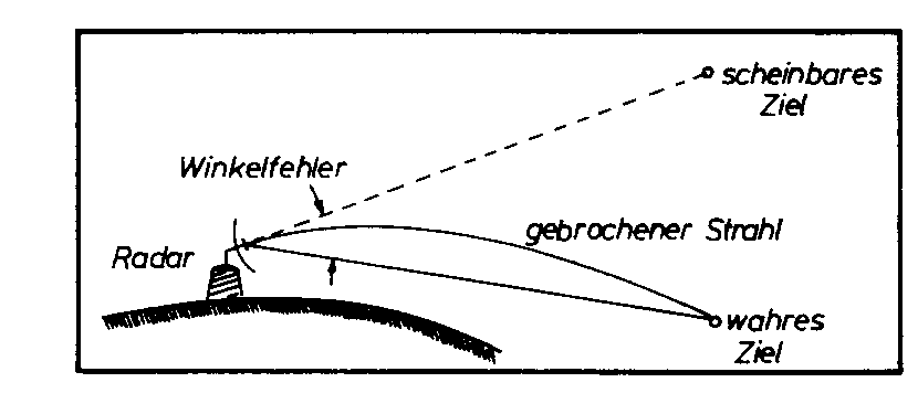
This drawing illustrates how refraction so to say ‘lift the moon’ a low moon elevation. To hit the moon at very low elevation angles we must radiate at little higher angle than the direct path to the moon.
This is why you can have echoes after moonset. The programs used for calculating moon position do not mention this, so I suspect they do not take this refraction into account. The effect is probably less than 1 degree and as our beams are not pencil sharp and our rotators not accurate to fractions of a degree we do not have to care unless we are on 10 GHz with a big dish. And in that case one would track the moon via moon noise, and then no problem with refraction.
A similar effect happens in the ionosphere but is hard to predict as the ionosphere changes ionization along the path of your eme signal in an unknown manner. The ionosphere may focus or defocus your signal and this effect is more pronounced at the lower frequencies.
Also for very low angles of radiation it must be considered that the earth is not flat but curved. For angles of radiation less than about 1º d will decrease and dF will decrease even more, but dN will be almost unchanged. This has not much practical importance.
In order to calculate the radiation angle from a QTH it is important to know where the ground reflection point will be and how much of the ground will contribute with reflections. This can be calculated by software. I know of the following packages doing this:
YTAD is freeware and described in QEX July 1995. This article tells much on radiation angles and calculation. The method and the shortcomings of the software are mentioned. This is important as most computer freaks think everything printed by computer is the truth. I hope you know better, after all this text is printed by computer…
YT is a newer and improved version of YTAD. Both programs are designed for HF use and the resolution is only 1 degree in the final plot although YT calculates for every ¼ degree. Both YTAD and YT includes important information on the statistically most needed radiation angles for HF propagation, but this has no relevance at VHF
Terrain Analysis (TA) has more options and a better display of the results than YT or YTAD. It is TA I use most but I sometimes verify my calculations by YTAD or YT. I have found all the programs give similar results. That is no wonder as the principal calculation method and diffraction theory behind the programs are the same. TA can model vertical polarization, YTAD and YT only does horizontal polarization. I might as well warn you right away, read the later chapter on polarization and you might conclude that vertical polarization and ground gain does not go too well together. If you insist on trying vertical polarization TA is the program to try. In TA you can set many parameters, you better read the manual and know what you are doing. For maximum accuracy I recommend you set 1/4 deg resolution, Slope consolidation 0.1 deg, Diffraction threshold -20 dB and over average ground.
The accuracy of these programs is likely to be better than +-3 dB, but do not stake all your money on more than 3 dB accuracy for the lowest loops where ground gain happens. The deep minima and the high angle loops around 90 degrees are not believed to be very accurate but this is of little interest to us. At least I do not care whether a minimum is –10 or –20 dB at a certain angle as there will be no QSO at that angle anyway. These programs are designed for HF and higher radiation angles and use less resolution than VHF amateurs could desire. Thus it the results should be evaluated and obvious unreasonable results discarded. This is noticed in the readme.doc’s.
Stacking, BLU switching and BIP/BOP phasing
The angle of radiation for horizontal polarization is only dependent of the antenna height over reflecting ground. Using stacked beams will concentrate the energy at the lowest radiation angle determined by the average antenna height, so stacking does not "pull down" the radiation angle significantly.
The vertical pattern in free space of a two-beam vertical stack is 1/2 of the single one, measured as the 3 dB opening angle. This angle is much different from the radiation angle. The radiation angle over reflecting ground is not lowered if both antennas are several wavelengths up and the center of the stack is at same height at the single antenna. But the stack will radiate more in the lowest loop, and give the theoretical 2.5 to 2.8 dB gain also at the lower part of the lowest loop.
If your mast height is fixed stacking will lower the average height of your stack by half the stacking distance. The radiation angle from the stack will then be higher than the radiation angle of the top beam alone. This is most noticeable at mast heights of only a few wavelengths. Stacking does not help much for radiation at very low angles = much lower than the lowest loop. It seems difficult (impossible?) to force energy into the lowest radiation angles if the mast is not high enough. The effect is very noticeable at 50 MHz where mast/towers seldom are very high measured in wavelengths.
If you want to control your radiation angle and have ground gain you must be able to change the height over ground of your antenna. It was done around 1942-43 where the Germans had a radar system for finding the height of enemy planes. The system ran around 222 MHz and employed antennas that were moved up and down between two masts to control the radiation angle. This is not very practical, how many eme antennas are on a remote controlled telescopic tower? But it can be done, there is one in PA0. A small antenna take advantage of 5-6 dB ground gain and sounds as a big antenna.
One trick could be to be able to switch between using only the upper or lower beam of a stack. HF-DX freaks know about a BLU-switch (Both, Upper, Lower). This could be supplemented by feeding one of the antennas 180º out of phase by switching in a ½ l phasing cable in one of the feedlines. This is called BIP/BOP phasing which stands for Both In Phase/Both Out of Phase. Most people who had tried out of phase stacking on HF reports that it is not productive, either beam alone or the stack is always better for low angle radiation (<10 degrees) as the antenna height used is seldom many wavelengths. For eme BLU and BOP might be useful on 50 MHz, but on the higher bands the needed relays will make exact phasing difficult.
For DX-ers on HF it is well known that the radiation angle of a horizontal polarized beam is a function of its height over the ground and ground conductivity has little influence on low angle of radiation. Things are different for vertical polarization. A vertical antenna needs perfect ground to give low angle of radiation. In fact is does not radiate at all below an angle called the Brewster angle. This angle is dependent of the conductivity of the reflecting ground. Check an antenna book on verticals for 80 m, the 80 m DX’ers know all about this. Does low angle of radiation interest us for VHF? Yes ground gain is happening in the range of 0-10 degrees.
|
Horizontal polarization |
Vertical polarization |
|
|
Ground gain for one reflection |
5-6 dB |
Perhaps 3 dB |
|
Ground conductivity |
Little influence at low angles |
No radiation below Brewster angle 5-20 degrees |
|
Lossy ground |
Little less ground gain and not so deep nulls in pattern |
High Brewster angle 20 degrees? |
|
Good ground conductivity (salt water) |
Deep nulls in pattern, but peak almost uninfluenced |
Low Brewster angle < 5 degrees? |
It seems a good idea to use horizontal polarization if one wants low angle of radiation. Vertical polarization has less ground gain. A circular polarized signal contains two components: a horizontal polarized and a vertical polarized one. Ground reflection influence the two components differently as describes above and after ground reflection the signal is no longer circular but somewhat elliptical polarized at low radiation angles.
Ground gain is available at VHF for low angle radiation and horizontal polarized antennas at heights of app. 1-5 wavelengths. Ground gain can be 5-6 dB and is easily estimated over flat ground using simple formula or monograms. For non-flat ground QTH’s (=hilltop I hope), things gets quite complicated but ground gain can be calculated with reasonable accuracy by software designed for amateur radio use at HF.
In order to get ground gain your beam must illuminate the ground. For low angle eme up to 5-10 degrees your elevation rotator should show zero degrees depending on your antenna height and terrain. On a hilltop QTH a negative elevation that is beaming along the downward slope might result in best ground gain.
Several angles apply to antennas over ground:
Ground effects favor horizontal polarization for low angle radiation.
Acknowledgments
Many people helped providing the basis for this text. It was fun to write, but no easy crack. It was originally done for the Weinheim VHF/UHF convention 1998 in Germany. Food provided by Mac Donald’s, beverages by the Coca-Cola Company and the midnight oil burned using Brazilian coffee .... .. Greets to
Brian Beezley, K6STI for developing Terrain Analyzer
Dean Straw, N6BV for developing YTAD and YT
Microsoft for the possibility of getting nice WareZ: Win95, Word 97 and PowerPoint97, later replaced by XP
Intel for a VHF Pentium (150 MHz) with later improvements to UHF (300 MHz)
Compaq for fitting above in a LTE 5000 and Armada notebook
OZ5W/OZ9EDR contest team for trying out many QTH’s and putting up some pretty big /P antennas for evaluation during contests. Behind the scene is Torben, OZ1BGZ who creates many fancy mechanical details with an accuracy which usually only exists in the logical world. Software may help, but some antenna hardware is needed to create radiation!
E. Fich and R. Ruddlesden, "The choice of aerial height for ionospheric scatter links", Proc. IEE, vol. 105, pt. B, suppl. 8, January 1958, p. 12-18 ¬
the whole volume is 200 pages of interesting stuff on tropo- and ionoscatter propagationThe scatter propagation Issue: Proc. of the IRE, October 1955, p. 1175-1298 ff.
R.G. Merrill, "Optimum Antenna Height for Ionospheric Scatter Communication", IRE Transactions on Communications Systems, March 1960, p. 14-19
R.G. Merrill, "Radiation Pattern in the Lower Ionosphere And Fresnel Zones for Elevated Antennas Over a Spherical Earth", National Bureau of Standards Monograph 38, 1962
David, P. (1969), Propagation of Waves
E. Baur, Einfürung in die Radartechnik, ISBN 3-519-00106-3, Stuttgart 1985
R. Dean Straw, N6BV, "The Effect of Local terrain on HF Launch Angles", QEX, July 1995, p. 3-15
Brian Beezley, K6STI, ta.doc Documentation for TA 1.0 TERRAIN ANALYZER 1995 by K6STI
A little advertising is coming your way also. My practical experience with radiation angles comes from contesting where antennas and propagation can be judged and compared with the other combatants. OZ5W/OZ9EDR contest team tries to make DX QSO’s regardless of band conditions, but we need someone at the other end to make a QSO. Please try looking for OZ9EDR or OZ5W in major contests and 19-23H local time:
1.st Tuesday of the month: 144.280 SSB/CW +.305 2x8874+GU78b 2x18elm M2+2/4x9elm
2.nd Tuesday of the month: 432.180 SSB/CW 3CX800A/4CX400A 4x28elm+2x38elm
3.rd Tuesday of the month: 1296.180 SSB/CW OZ1BGZ 70 W at 4x37 elm JO65AP
4.th Tuesday of the month: 50.160 SSB/CW 2x8874 1kW 2x6elm /P JO55KR
We mostly have one beam to the south (DL and PA0) shortly after 19H local and to the northeast (SM and OH) around 21H local. We do troposcatter QSO up to 700 km and on 50.160 meteorscatter from 1.100-1.600 km. Skeds may be arranged. Please exchange full 6-digit locator. We are in JO55UL or /P likely at JO64GX or JO55KR.
I can be contacted at:
|
E-mail: palle -at- oz1rh.com Phone: +45 46 78 77 67 GSM: +45 40 36 77 67 +45 29 23 60 72 |
Snailmail: Palle Preben-Hansen Soderupvej 104 Ågerup Mølle DK-4000 Denmark |
Sri no packet, life is too short for QRP and 1200 bps!
© OZ1RH