ON7YD
Vertical antenna with inductive toploading
In an environement with a lot of 'vertical objects' (trees etc.) close to the antenna inductive toploading can significantly increase the performance of a short vertical antenna.
In december 1999 I improved my 136kHz antenna by placing a part of the loading coil at the top of the vertical part. To my own suprise the improvement was much more than expected, from calculations and simulations an improvement of about 0.5dB was expected (due to better current distribution) but measurents by PA0SE and DK8KW showed an increase of about 4dB.
Old antenna configuration :
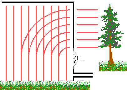
I think that this unexpected improvement can be explained by the fact that a part of the electric field of the antenna was not directly to the ground, between the vertical part of the antenna and the many surrounding (mainly vertical) trees. This field is parallel to the ground and will not contribute in the radiation.
New antenna configuration :
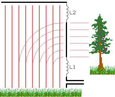
Placing a part of the loadingcoil at the top of the vertical section will reduce the voltage on the vertical section. In my case about 50% of the total loadingcoil was placed at the top, reducing the voltage on the vertical section by roughly 50%. The result is a decrease of electric field toward the surrounding trees and, as the input power to the antenna remained almost unchanged, a stronger electric field directly towards the ground.
At least 2 others (DF3LP and G3XDV) achieved similar results by inductive toploading and both have also a lot of 'vertical objects' close to the antenna. Another ham who has a vertical antenna without 'vertical objects' nearby could not get a significant improvement by using inductive toploading.
The picture below show a drawing of my antenna setup. Since there are many trees arround I use 4 of them to support the antenna.
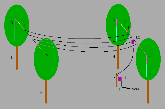
The antenna is 14m high at the right end (where the loading coil is) and 16m high at the left end. The horizontal top section is 22m long and consists of 4 parallel wires, each 90cm separated.
Legend :
I = isolator (10cm long, ceramic)
L1 = 2.3mH loading coil
L2 = 1.9mH loading coil
N = nylon rope (4mm diameter)
P = 2.5m wooden pole
S = flexible steel cable (2mm, plastic covered)
T = transformer (impedance matching)
X = 'stretcher' (the elastic thing you use to pack something on the back of a bicycle)
The stretchers are used to 'absorb' the movements of the trees (the combination of strong wind and Murphy's Law will always let the trees move in opposite directions).
Where the ropes that hold the antenna can cause friction with the branches the nylon ropes is replaced by a piece of flexible steel cable.
You are visitor number  since 21 feb. 2000
back to previous page
since 21 feb. 2000
back to previous page