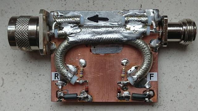
Directional coupler PCB. Left connector is output, right connector is input. 'F' terminal is forward power, 'R' is reflected.
For my home brew 432 MHz 500W EME power amplifier, built around 2 refurbished TV LDMOS-pallets of 250W each, and controlled by ARDUINO, i was in need of a good and accurate directional coupler. Not only to protect the PA against excessive SWR, but as well to display and monitor the actual SWR in the most accurate manner possible. This is particularly desirable for an antenna system consisting of an array, in order to detect any anomaly with only one antenna for example, what would result in a small deviation of the normal SWR.
The directional coupler was built on a small piece of double sided PCB, 65mm long and 55 mm wide. N connectors were soldered at the side, directly to the PCB upper and under sides, providing a rigid assembly.
Between both N connectors, a small length of 50 Ohm semi rigid coax (with Teflon dielectric) is soldered. Of this coax, about 30 mm length of outer shield is grinded away, over a width of about 2,5 to 3.0mm. Same type of semi-rigid, where similar sleeve has been grinded, is used as pick-up and soldered tightly against the straight coax between IN and OUT. The outer shield was grinded away with an small angle grinder and then trimmed with a small file, but probably a DREMEL tool could be used as well.
Directional coupler PCB. Left connector is output, right connector is input.
'F' terminal is forward power, 'R' is reflected.
Now it is essential to compensate IN and OUT terminations for the small inductance due to semi rigid coax to N-connector joint. With no compensation, the coupler has a SWR of 1:1,3 on 432 MHz, much too high ! The stray inductance can be compensated by a small capacitor, formed by a length of same semi rigid coax. The insertion length of the center of this coax can be adjusted to precisely compensate and obtain a perfect SWR - I measured on the FieldFox VNA 1:1,02 on 432 MHz.
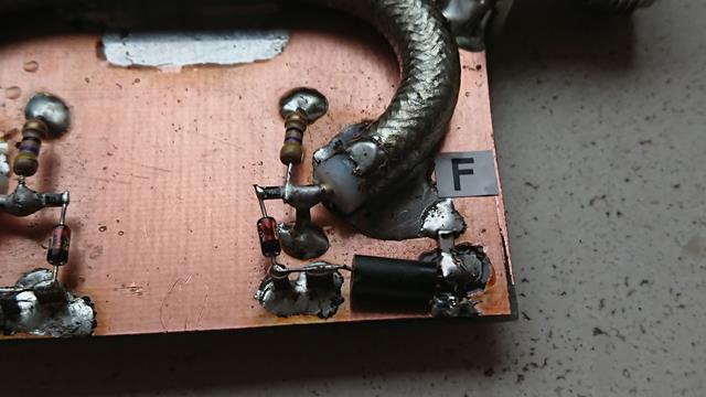
Both ends of the pickup coax are terminated by 0,25W 47R or 51R carbon film resistors, these are able to dissipate the picked-up power. At the end of the coax, a 150R SMD resistor in series with 1N4148 diode rectifies the RF voltage, which is decoupled by a 82pF (non critical value ...- and 100nF chip capacitor. For even better RF decoupling, I used ferrite beads and a 1nF capacitor at the sense outputs, where a 47k SMD resistor acts as a bleeder.
A directional coupler is characterized by two main values : coupling factor and directivity.
The coupling factor determines how much power is sampled from forward & reflected signals. With this construction, I measured on the FieldFox VNA -33dB. So with 500W RF, about 250mW is sampled.
The directivity determines the ability to make the difference between forward and reflected signals. In order to be able to measure with precision a good SWR, this value should be as high as possible, minimum 20dB, better 30dB. With 20dB, you will not be able to measure a SWR better than 1:1,2 about, with 30 dB it will be 1:1,06, with 40 dB 1:1,02.
During construction of the SWR directional coupler it became clear that, to obtain the best possible directivity on the 'reflected' output, the forward end of the pickup line must be properly terminated. By using just a 47R resistor (as shown in pictures), the directivity was about 20dB. However, by compensating capacitively this same end, this could be increased to about 40dB ! Ideally, a small trimmer capacitor should be provided - but I was satisfied by using a fixed SMD chip capacitor of 2,2pF, resulting in a directivity of just over 30dB.

Detail of forward end pickup line
To measure the directivity, just use your VNA connected with port 1 on the directional coupler input, on the output mount a 50R calibration resistor, and measure S21 with VNA port 2 connected to the 'reflected' end of the pickup line (while removing the 47R resistor). Any adjustment or compensation of the reflected end of the pickup line has very little effect on directivity - it is the forward end which must be well matched !
Directivity was finally tested while applying 500W RF power to the coupler, connected to a dummy load. On the forward terminal 3,1V DC was measured, perfect to feed directly to ARDUINO ADC input, on the reflected terminal only a couple of mV ...
Off course for 144 Mhz / 2m band same construction principles can be considered. The coupling will depend on frequency - for lower frequencies, less coupling will be observed. Coupling can be adjusted by varying the length of sleeve between main coax line and pickup line.