Inverted-L for 80m & 160m

I wanted to test a temporary / portable setup to participate in 80 / 160m contests.

The antenna is inspired on the 'Battlecreek Special' design, but then limited to 80 and 160m (no 40m section). It is a further development of the 80m full size GPA described on another page of my site, allowing dual band operation.

Results:

On 80m very good performances with very acceptable noise level. Made several comparisons with EWE antenna's and magnetic loops -  the very weak stations were always readable on the GPA... Bandwidth for SWR 1.5:1 is 80 kHz,  for 2:1 125 kHz, for 3:1 is 200 kHz. Worked a lot of DX without efforts.

On 160m  good performances, I could only test this in SSB, despite the fact that topband is a CW band! Noise level S7 about (BW 2,2 kHz). Worked several stations in USA and S. America (Brazil, Nicaragua) with 800w PEP. Bandwidth for SWR 1.5:1 is 20 kHz,  for 2:1 30 kHz, for 3:1 is 50 kHz. The resonance frequency can be shifted upwards smoothly by 50 kHz or so by giving some slack in the 'L' section, so adjust your antenna with the L-leg taut in the lower region of desired operation (with this slack in the 'L' section, resonance shifts up on 80m by only 10 kHz)
 
  The 18m glassfibre pole from SPIDERBEAM is used, but without the top section (too fragile to support the weight / wind load of the 80m trap coil). The antenna itself is composed of 12m of heavy flexible insulated copper wire 4mm² section + 7m of same but 2,5 mm² on the top. This (about) 19m wire is tightly wound around the pole (pitch about 1 turn per 2m). The same base as for the 80m full size GPA is used, with 96 radials of about 10m length.
  The 80m coax trap coil. This is wound on a 80mm dia PVC light-weight pipe, about 9,8 turns required. I first made one with RG-58, but had a flash-over between the insulation and a terminal bolt (800w PEP). Second version with RG-400 (Teflon Coax) was a lot more reliable, but somewhat heavier in weight. The 'L' section is about 15m50 long, made of (light weight) 0,75mm² PVC insulated  flexible copper wire. I affixed this to the roof of the house, about 10m high and 25m from the GPA (so it is slanted). It makes no sense to give you the exact dimensions, as these will vary in function of the trap construction and it's resonance frequency, and the possible slant of the 'L' leg.
   

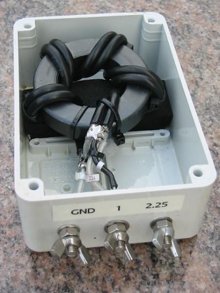
As a GPA has a low feed resistance (about 35R at 1/4 wave, about 20R as shortened on 160m), the antenna is fed through a 1 to 2,25 balun to feed it by 50R coax. The balun is wound (5 or 6 turns bifilar) on a large 43 material ferrite core, here with RG-58 (no problems with 800w), but better would be RG-400 (this coax is rated at 5 kW). The result is a very flat SWR curve and 1:1 at resonance. You can find details how to construct this balun on the valuable site of  ON9CVD Bob This balun is normally used to step up impedance from 50R to 112.5R, but can be used to step down as well !