MOTOROLA GP-300 is available on the market in many different versions, I had the chance to salvage from the scrap container a model VHF , 16 CH, with keypad, frequency range 146-174 MHz and RF power up to 6W (Many thanks Alain !)
The rugged radio comes standard with a NiCd battery HNN9628 of 1200 mAh. Equivalent batteries are available as NiMh 1.500 mAh (can be charged with the standard drop-in charger) or even a Li-ion type of 2.700 mAh (with dedicated charger).
The standard rubber duck can be replaced by a more 'sexy' Diamond HC-100-M antenna, which can be precisely frequency cut to 145 MHz,. The radio is very sensitive on RX, and on TX I programmed all channels for medium power output (which is about 1.5W) in order to conserve battery power.
The radio can easily be reprogrammed inside the 2m HAM band using the RSS ( I am using GP-300 5-tone RSS version R02.04.00 - sorry but I cannot provide it - but use Google to find the nearest Motorola distributor)
This is the trick to enter frequencies outside of radio band: to validate entry, PRESS SHIFT + F2 --> cursor will jump to next field. When table entry is finished, accept the 'warning message' !
It is possible to define a CTCSS (TX and RX), repeater offset, 1750 tone burst, roger beep, power save function, scan table, send DTMF tones... Feel free to download my radio profile here as example and possible start for your own configuration.
Build your own programming interface
Instead of the MOTOROLA RIB (Radio Interface Box) and cables, you can easily build your own interface out of junk box parts - see attached information (PDF)
Many thanks for EB4EQA for proving the cut-out of a PCB which can be inserted instead of a battery. In the PDF document, the dimensions should be OK (check!) when printed on A4 paper. Pay particular attention to the mods required for the RS-232 to MOTOROLA Bus interface of Igor KARPENKO, else mine would not work.
In the interface box, I provided a µA7808 voltage regulator in order to eliminate the need of a battery while programming and allowing all to run from 13,8v. Make sure the IC is mounted on the metallic cabinet to provide some cooling, as during transmit it will heat up.
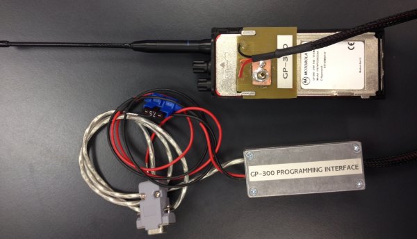
GP-300 with interface / power box
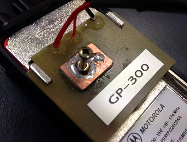
Detail of connecting PCB.
When slid in position, the M3 screw (hand tightened only) will make
contact with the underlying BUS connection and keep the PCB in place
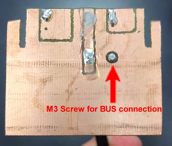
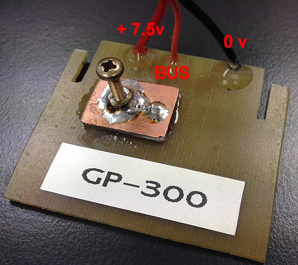
Back side of PCB. Take care that no solder is protruding too much, in particular the + 7.5v !
PCB front side