When I moved to our nice new QTH in a residential area, where our garden is about 15mx15m, what to put as HF antenna ?
Well, it is possible to erect a multiband vertical right in the middle, with a good grounding of at least 50 buried radials - this is what I have foreseen for 'contesting operation'.
But, as a matter of facts, this is not the most superb and nice view for a permanent setup.... therefore I was looking out for an alternative, a multiband antenna with decent efficiency, able to withstand QRO power, and with the least visual hinder possible for me, the XYL (HI) and neighbors ;o)
The idea was to set up an EFHW as inverted-L : from the feedpoint at the edge of property, about 10m upwards into the direction roof ridge, then bent in a 90° angle sloping downwards for 10m towards the garden house, so in total about 20m in length.
According to different 'classical' designs you can find on the Web, this could be operated from 10m to 40m, and in addition on 80m by adding a 110µH loading coil + tail wire of about 2m length at the end.
First tests showed that antenna was operating quite well, about same results as the Butternut HF6 vertical, but on 80m the bandwidth was extremely narrow - about 20 kHz only for SWR < 3:1. So maybe useable for FT8, or in DX segment only, but certainly not for contesting... Also, the 110µH loading was a problem for running QRO. A first 'light duty' version burned (flashover between adjacent windings), a second 'heavy duty' version, with windings well interspaced, was not stable: the SWR fluctuated heavily in function of power applied ... so another approach was required to operate on this band.
As we have a wire length of 20m, why not try use it as a 1/4 wave instead of 'end feeding' it as a half wave? This would require a good ground as counterpoise, but that was not a problem, as I had provided this already for the EFHW feedpoint by a copper strip of 25mm wide, ground rod and nets.
Measurements with the VNA showed that this was feasible, but the antenna was at resonance somewhat too inductive. This was compensated by putting a capacitor of 270pF to ground at the feedpoint, which then brought the dip nicely @ 3700 kHz and the SWR below 2.0 between 3.600 and 3.800 kHz - perfect for the PA ATU !
And QRO operation was perfectly possible !
So it was required to provide 2 relays to switch over:
These two relays are automatically actuated by a simple band decoder circuit detecting when 80m is selected.
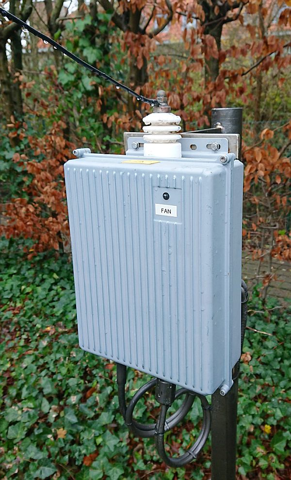
The EFHW transformer box from outside. One
cable is the coax feedline,
the second is the supply to the cooling fan and control of relays.
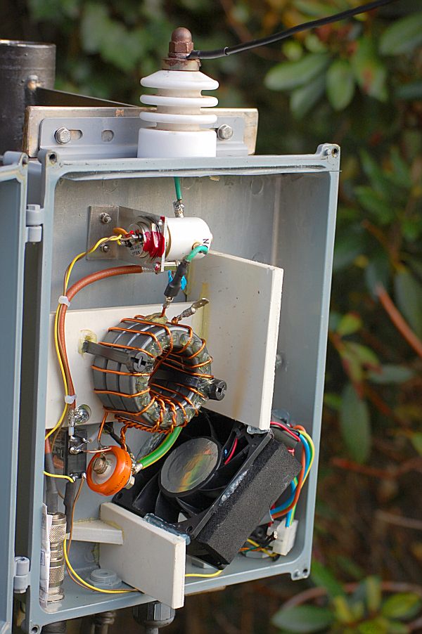
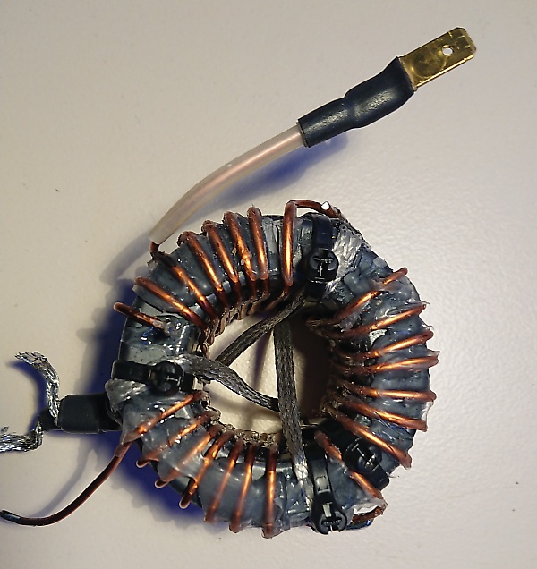
The 1:64 transformer is wound on 3 stacked
FT240-52 toroids, this provides same inductance
as one FT240-43 and is able to withstand 1kW 50/50%
duty cycle with help of a cooling fan...
which is only running during RX periods in order to avoid being damaged by RF field.
Curie temperature of Mix52 is > 250°C where that for Mix43 it is only about
130°C.
See further how to optimize windings on toroids !
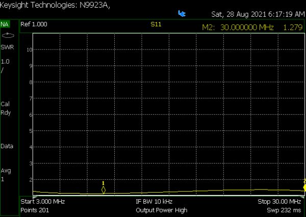
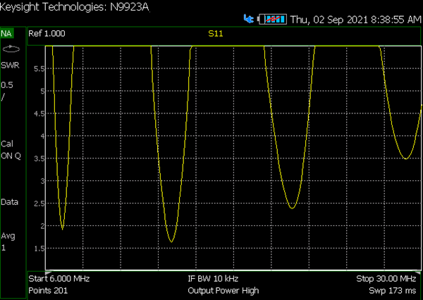
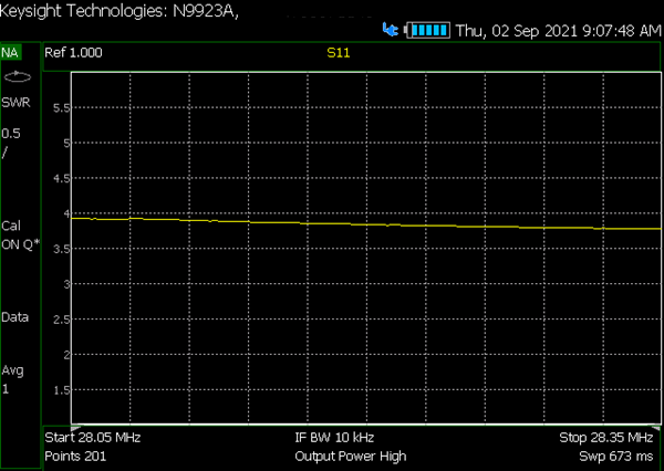
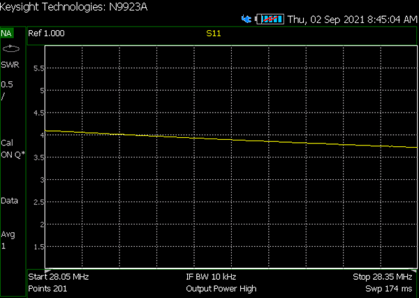
Hereby the SWR (S11) diagrams measured of my EFHW (as an 'inverted-L') with professional Agilent 'FIELDFOX' VNA, properly calibrated to cancel out the feedline (see below on webpage why this is important). As antenna wire, instead of the ordinary 1.5mm² PVC covered flexible and stranded electrical wire you see in pictures above, I am now using a special LITZE cable type HFW2, a combination of stainless steel core, with silver plated copper braid around (see specs here), which should provide better RF performances and be subject to no lengthening at all due to strain.
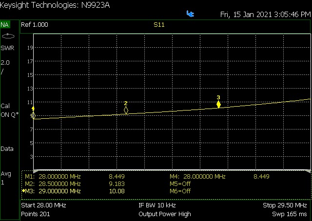
SWR at feedpoint is sky-high on 10m ...
but can still be matched by ATU, who- thanks to feedline losses - 'sees' a
SWR
of 3:1 at end of the feedline ! Poor performances as a
DX antenna, however perfect for Es continental contacts!
See further how to improve SWR on 10 & 15m bands by optimizing windings
on toroids !
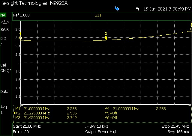
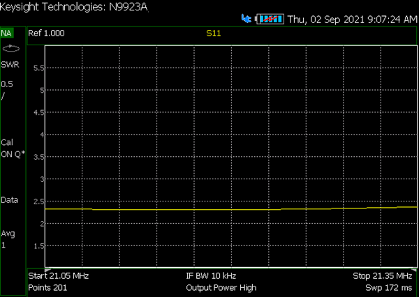
On 15m marginal performances as DX antenna. SWR measured at end of feedline 1,7:1
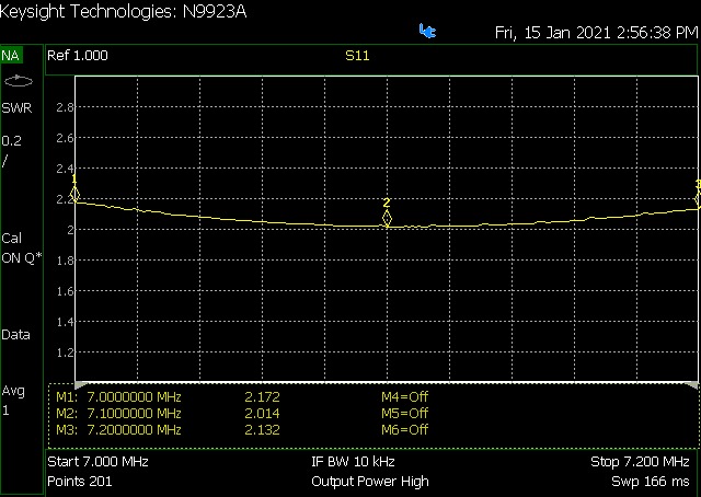
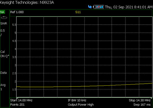
Good performances on 20m for DX and continental contacts ! It is not a 6 element beam, but all you can hear, you can work !
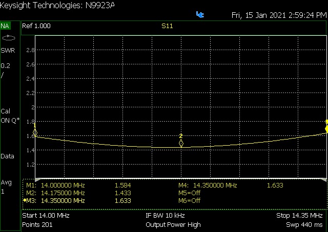
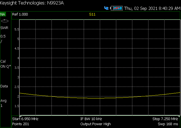
Good performances on 40m for DX and continental contacts ! SWR at end of feedline measured as 1,4:1
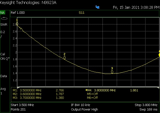
Operating as 1/4 wave on 80m, sweet spot @ 3.7
MHz as I mainly operate SSB. Excellent NVIS antenna, very good for
continental contacts and quite OK to work the stronger DX stations. SWR at end
of feedline measured as 1,4:1
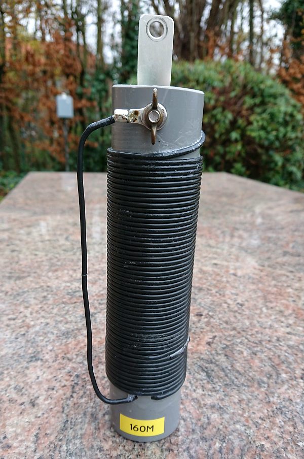
Yes sure ! By inserting a base loading coil in the '80m configuration', operation on 160m is possible. Coil should be about 43 µH (in my case!), this was realized by about 52 windings of 1.5 mm² PVC covered wire on a 50mm diameter PVC pipe. This results in about 100 kHz bandwidth with SWR < 3:1, which can be handled by the PA ATU. As I only operate from time to time on topband, the loading coil is manually inserted when required...
Operation on 60m band is as well possible ! By modeling with EzNEC found that be inserting a capacitor of 65 pF in series with the 20m radiator at it's feedpoint, resonance shifts from 3.7 MHz to 5.4 MHz - what was effectively confirmed by using a variable air capacitor. This variable capacitor was replaced by a 68 pF / 6 kV 'doorknob' type, SWR at end of 25m RG-213 is well below 2:1, what can be matched perfectly by ATU.
Very often you will see published quite nice SWR or Return Loss (RL) curves ... sometimes, manufacturers indicate that the measurement is performed at the end of 'XXX meters of type YYY coax cable', sometimes HAMs announce that the measurement was made 'at the transceiver connector, without using any antenna matcher' ... but regretfully, this data is of little value to indicate if the antenna is well matched !
If you measure the SWR at end of feed line, it will always be better than at antenna feed point. This is due to feed line losses, considered in the TWO directions (for forward and reflected waves). In my case feed line losses on 28 MHz are about 1.5dB 'forward' (as measured or calculated with coax specifications) and off course 1.5 dB 'reverse' or 'reflected' = 3 dB in total. This will add to the return loss measured at feed point: on 28 Mhz: a SWR 9:1 equals to RL of about 2dB + 3 dB feed line loss = 5 dB RL at end of feed line = SWR 3,5:1, what can easily be matched by ATU of my PA. As conclusion, I can say a big 'thank you' to my RG-213 coax line, being lucky not to have put 1/4" CELLFLEX line or better ... !
But why is the SWR so bad on 10m band ?
Possibly due to the 'inverted-L' configuration instead of straight antenna, or characteristics of toroid transformer. I measured on 40, 15 and 10m bands antenna is capacitive, on 10m even 'very' capacitive - so maybe on 10m the 110 pF capacitor is over compensating ? However on contrary on 20m the antenna is inductive .... So at time being it is a compromise between all bands, with a favor for best performance on 80-40-20m. Terrain lies open for further experimentation !
Any hint/suggestion for further optimization from other HAM's would be much appreciated ;o)
Daniel Marks KW4TI, has published a very interesting paper about 'leakage inductance' which attracted my interest (download it here). What is 'leakage inductance' ? Well, when the secondary of an ideal transformer is short-circuited, the primary should as well provide a short circuit - the difference with actual value measured being the leakage inductance. In industrial (power supply) transformer, a leakage inductance is intentionally introduced, as a protective measure should the secondary been short circuited.
I made some tests adopting the 'interleaved' winding technique suggested by KW4TI with one FT240-43 toroid and a 3:21 windings (1:49 ratio) and could obtain an almost flat frequency response from 3 to 30 Mhz with a 85 pF compensation capacitor - in this case the leakage inductance was about 0,36 nH.
This was far better than the 'classic' winding technique - with the 3 first turns wound bifilar and 21 windings on either side of primary, wide spread over complete circumference - where 0,7 nH was measured and 0,48 nH when windings wound as tight/compact as possible (about 40% of circumference). Best value for compensation capacitor was always 82 to 85 pF, 100 pF was clearly over compensating and resulting in a higher SWR on 10m. Best SWR on 30 MHz with optimal compensation was about 4:1 with windings wide spread over circumference and a 1,2:1 with tight wound transformer, all measurements performed on the work bench with an adjustable low inductance resistor on the transformer secondary.
Conclusion : the leakage inductance / winding technique has an effect on frequency response on the high bands.
Now, with 3x FT240-52 toroids stacked the results were not in line with those of a single FT240-43....
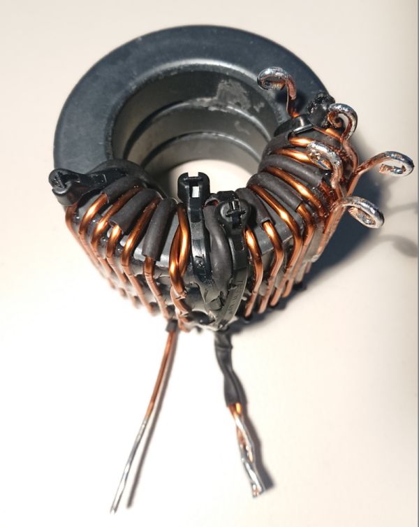
I have wound a transformer with 3 primary windings 'interleaved' with 3x 7 windings secondary, the leakage inductance was much lower than the 2:14 'wide spread' version. The frequency response - measured on my work bench - on the high end improved somewhat, but when tested 'real life' it was not performing as expected.
The SWR was somewhat better than the 2:14 'wide spread', but the length of antenna wire had to be shortened by 60 cm to have it resonating on 40 to 10m, and this caused problems for 80m (becoming too short). So, this transformer was finally not used ....
In an attempt to minimize leakage inductance, I assembled a transformer with 2:14 windings, wound as close as possible - occupying less than 50% of circumference. Leakage inductance was indeed very low, about 0,22 nH, even better than the 3:3x7 model pictured above.
Test in 'real life' did however not provide the expected results, SWR on 10m was certainly better than the 'wide wound' version, but still quite high, despite trying to adjust the compensation capacitor and the secondary tap-off.
Finally the best results have been obtained with a 2:14 transformer (2 primary bifilar, 2x 7 secondary) and windings wound more compact, on about 50% of circumference (instead of 100%) and a 100 pF capacitor This provided best results in 'real life' operation - SWR on 10m band went down from 9:1 to 3,5:1 . See picture below.

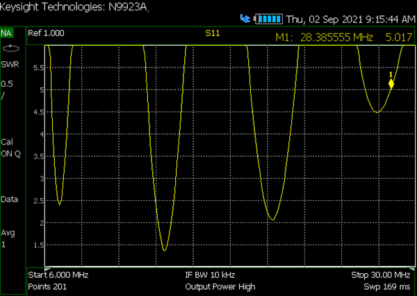
Very compact winding - SWR 6 - 30 MHz
Compact winding - SWR 6 - 30 MHz

Very compact winding - SWR 40m band
Compact winding - SWR 40m band

Very compact winding - SWR 20m band
Compact winding - SWR 20m band
Very compact winding - SWR 15m band

Compact winding - SWR 15m band
Very compact winding - SWR 10m band
Compact winding - SWR 10m band
After 3 years of operation, the overall performance can be outlined as follows :