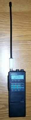
RE-A144V1P
"MUrDuck" VHF "rubber duck" Portable Antenna
RE-A144V1P
de ON6MU
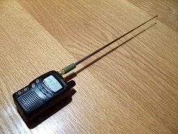
You can make your own 2-meter "rubber duckies" that will likely perform much better than many commercial units. I compared my design with two other "rubber duckies" of the TH215 and ICT7 which outperformed them both. With the "duckie" of the ICT7e as much as 10dB. It does not has a gain compared to a 1/4wave antenna ofcourse, but compared to most standard "rubber duckies" its average "gain" is about 6dB (or more). This has several reasons:
This design is based on using a maximum applied RF power of 15 W at 144 to 148 MHz.
To test and tune you need:
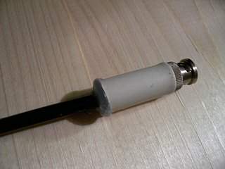
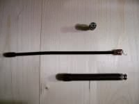 |
BNC Half finished TH215 duckie |
Results in practice, tested at five different positions:
| Position | ICT7e ant (10cm) |
MUrDuck 1/8 wave |
Kenwood
1/4 telescopic ant |
| A | S 4 | S 9+ | S 9+6dB |
| B | S 7 | S 9+12dB | S 9+15dB |
| C | S 3 | S 8 | S 9 |
| D | S 5 | S 8 | S 9 |
| E | S 9+6dB | S 9+20dB | S 9+30dB |
Transmitter: Icom ICT7e @ 0,5
watt
Location: City, inside building, 1Km
Receiver: Kenwood TM255
Location: City, 2x5/8 comet @ 18mASL
Conclusion: Our "MUrDuck
1/8 wave duckie" performs much better then the standard Icom
ICT7e dualband duckie but does not beat a the quarter wave
Kenwood dualband telescopic antenna. Although the results between
the quarter wave and the "MUrDuck" are very close, the
measurements between the factory ICT7e duck-antenna are quite
impressive!
Note: the S-readings are not calibrated readings!!!
What you need to build the MUrDuck (RE-A144V1P):
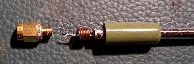
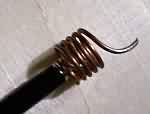 |
Wind 5 turns of 1mm wire around a coil form of 10mm diameter, keeping the turns about 0.5mm apart. This will fit snugly into the 5/8" PVC tube. |
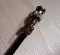 |
The is coax soldered to the coil and the coil is soldered to the centre pin of the BNC. Solder it to the coax (if you use a coax as antenna): The center conductor and the shield of bothe sides of the coax is connected together. Cut if needed (optimal SWR). Mine was cut to 24 cm. |
To Test
For optimal performance, use a
VHF SWR/power meter and a field-strength meter to tune the
antenna. If you don’t, your
homemade antenna may still work at least as well as the factory
antenna. I used a Daiwa SWR meter and a "homebrewed"
field-strength meter positioned about eight feet away from the
transceiver. Connect your new antenna to the SWR/power meter
using the proper combination of connectors.
(A right-angle SO-239 adapter and a PL-259-to-female BNC adapter
worked for me.)
Attach the radio’s antenna
output to the SWR meter’s transmitter input with a 60cm (or
shorter) length of coaxial cable.
Adjust the field-strength meter’s location and its antenna
for a mid-scale reading.
Connect your commercial rubber ducky to the SWR/power meter and
check the antenna’s performance; log your measurements.
Those are the numbers you’re going to beat. We’re
looking for minimum SWR, maximum power and maximum field
strength.
Now, attach your homemade
antenna to the SWR meter. Check the antenna’s SWR and field
strength. Gently adjust the
vertical position of the whip until there is an improvement in
the readings if needed. Try squeezing the coil turns closer to
each other which influences the SWR too. Continue making
adjustments until the readings are optimized.
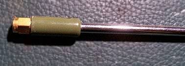
Once you are satisfied, run a
bead of glue around the base of the whip. Place
the 3cm 5/8" PVC pipe over the coil, overlapping both ends
of the coil form and leaving enough space to push in the BNC
connector and room to fill the rest up with glue of a glue-gun.
You can see the BNC-connector which is pushed in the PVC-pipe by
carefully heating up the end of the 3 cm long PVC 5/8" tube.
After checking the SWR it's filled with glue from a glue-gun
which gives it the solid-state and durable finish (and
watertight).
I've managed to get the SWR to
1:1!
A few last things to note. A small antenna such as a rubber duck
antenna (or even a mag-mount antenna) attached directly to a
radio will give different results based on the size of the radio,
what's connected to it, and the things around it. The reason for
this is that the antenna tuning is affected by the
"counterpoise", which in the case of a rubber duck is
the radio itself. (If the antenna is outside or better isolated
from the radio, the readings should be the same.) Since things
like rubber ducks won't be the same with an outboard SWR meter
connected or the same as an antenna analyzer might show, the only
way to know what the SWR is for a particular radio and frequency
with a particular configuration of power supply, microphone,
people etc, is to read the SWR off the radio. Of course if that's
not accurate, you're not getting the right information.
More of interest:
The
Telescopic MurDuck
RE-A144V2P
Same principle, but using a
telescopic antenna of 30 cm in length. Being telescopic it can be
used for more then one frequency. I also put a 3 pF capacitor
inside the coil and soldered on both ends of the coil (making it
parallel resonant). The "block" frequency lies way out
of the VHF or UHF HAM bands. 144...148 or 420...440mc are easily
passed through, making it dualband. The frequency that's being
blocked is about 290 Mc +/-.
Instead of a BNC connector I used a SMA connector.
Coil dimensions: 6.5 turns, 4mm inside diameter, 0.6mm wire (+/-
100nH)
Inside the coil: a 3pF capacitor
 finished
I used a SMA connector for use with my Yaesu VX-1. The included
"petite" rubber duck isn't worth much.
This has made a huge difference not only for VHF/UHF, but also
outside the ham-bands as this little VX-1 thingy has wide
reception.
To test and tune your telescopic dualband antenna the same principles described above (MurDuck) applies here too.
The tank resonance formule: 2*pi*F= 1/sqrt(L*C) => 291 Mc block frequency
Have fun and my best 73"
Guy, ON6MU
http://www.qsl.net/on6mu
Home
www.qsl.net/on6mu
![]()