RF Powermeter / dummy load
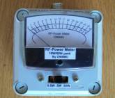
By Guy, de ON6MU
rev1.2
![]()
RF
Powermeter / dummy load
By Guy, de ON6MU
rev1.2
About the power meter / dummy load
A 50 Ohm dummyload is an essential part for any radioamateur as is a powermeter. The prices of such relative simple equipment is expensive, but not for us handy Hams HI. All you need is a metal box (or plastic box painted inside with graphite or other conducting/RF-shielding capable material), a few resistors and basic components (which can be salvaged from old radio's, switching power supplies etc..) and a analog meter. I used a Radio-shack meter, but any (sensitive) meter can be used. It's all a matter of calibrating your meter correctly, which is easy if you can lend a good commercial RF power meter.
This RF-power meter combined with build-in dummy load is made to measure power levels starting from a few milliwatt up to 50 watts (or more if suitable components are used and an avalanche sinterglass diode). IT has 3 scale readings: 0.5 watt, 5 watt and 50 watts. Again, you can extend the scales easily. The power meter is ideal for measuring QRP levels and by adding an BNC connector you'll have an easy oscilloscope measuring point.
In short, an easy and cheap project to build yourself. Even a beginner in HAM homebrewing can make his own fair (if not better then most you buy in the shop) power meter!
Calibration
Is done with a good (commercial or already calibrated) SWR/RF powermeter capable of measuring HF power levels from 5 (or less) to 50 watts and has a frequency range that covers the entire HF-band. You also need a transceiver which you set in series with the meter: TRX -> COMMERCIAL RF METER -> ON6MU RF METER. Set all potentiometers (R2,R3,R4) to maximum resistance. Choose one of the scales (0.5, 5 or 50 watts) to start with. Other power levels/scales with the same step (X1 X10 X100) will have the same indication multiplied. So if you choose scale 2 being 5 watt and calibrate at least 5 power levels of your transceiver it should be ok for the other scale selections. Set R3 for full scale at 5 watt and work your way down. One calibration for all power level settings respectively is sufficient.
You can of course
use an oscilloscope or RF voltmeter to calibrate the RF
powermeter.
online: https://www.pasternack.com/t-calculator-power-conv.aspx
![]() volt
volt
Examples:
1W = 30dBm = 10V = 20Vpp)
100mW = 20dBm = 3.16V = 6324mVpp
50mW = 16.99dBm = 2.23V = 4472 mVpp
5mW = 6,99dBm = 0,7V = 1,4mVpp
U = Uv *2 = SQR(Uv)
Schematic fig1
Parts list
alu box (or plastic box painted inside with graphite) of 100mm X 100mm X 50mm
1 female PL 259 chassis (SO239)
1 connector to be used as oscilloscope measuring point
Analog Meter (as sensitive as possible and calibrate the scale with a good powermeter)
C1,C3 = 330pF
C2,C4 = 47nF high quality
C5 = 100nF
C6 = 10uF/6v tantal
D1,D2 =
BYW54...BYW56 (up to 500watt measurements) rev1.2. I used
a BYW55 controled avalance rectifier
..........= or 1N1448 if you do not need to
measure more than 10 watt max
D4 = 1N1004 (protects the meter for voltages higher then 0.6 volts)
S1 = 3 pos. switch (or more if you want more power scales)
L Dr = 500uH or 1M Ohm carbon resistor 1 watt covered with 0,2mm Cul 3 times (or more) turned over the length of the resistor
R1 = 18k
R2 = 100k variable resistor
R3 = 250k variable resistor
R4 = 1M variable resistor
R5 = 47...4k7 (optional; ideal should be configured as an attenuator if you add a connector to be used for measuring the RF with an oscilloscope, RF voltmeter, spectrum analyser...)
Rd = 50 Ohm Dummy load of at least 20 watt (see text)*
Specifications
precision power meter capable of measuring power scales of 500mW...100W+ (depending on the dummy load)
frequency range: entire HF band 100kHz...150Mc
switchable scale ranges (in this schematic 0.5W, 5W, 50Watts...)
oscilloscope measuring point
can be used as dummy load also HI
Note rev1.2*: sometimes the diodes broke when measuring 50watts. To measure power levels up to 100 watts or more a better diode (BYW55) has been used that is suitable for high voltages (Standard Avalanche Sinterglass Diode).
Inside the powermeter
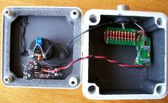
Dummy load
Is build out of 20 carbon resistors (or non inductive metalfilm) of 1K and 1Watt all parallel. I used two 15mm X 50mm print boards and soldered two times 10 resistors on each side. Solder the two parts on top of each other. See fig1 and 2. Do not use inductive type of resistors! Always use carbon based resistors or non inductive metalfilm ones. This dummy load is able to dissipate 21 watts continues and no problem to handle a 10 second peek of 50 watts. Long enough to measure the power. Be sure not to transmit high power > 21 watt for a long time as this will burn out your dummy load! IF you need the dummy load to handle more power then you could use 45 2k2 1 watt resistors which doubles the amount of power (and peek power). Of course you can use 1 k resistors of a higher power rating as long as they are non-inductive resistors.
fig.2.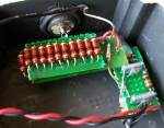
2nd
example:
RE-M3RFP Microwatt RF Powermeter
Parts list
shielded box
a BNC connector
D1 = 2 x ge diodes, like 1N34, 1N60, 1N270 or equivalents
C1 = 22nF
C2 = 100nF
C3 = 10uF
D2 = any si diode
S = switch that toggles betseen 50mW and 5mW (or any other scale you wanted). Switch Open = highest rating, in this case 50mW
M = a sensitive uV meter
R1 = 0,5 watt 47 Ohm non inductive resistor
P1 = 2k5 trimmer
P2 = 5k trimmer
Don't forget to check these out:
.ON6MU Homebrew projects
.Radioamateur related projects
.ON6MU software
.Lots of free software
73"