AM Mediumwave 50mW reference oscillator with buffer
RE-TX1MW05
By Guy, de ON6MU
![]()
AM
Mediumwave 50mW reference oscillator with buffer
RE-TX1MW05
By Guy, de ON6MU
About the 50mW MW AM oscillator
In this project, you will make a
simple 2-stage low-power broadcast-type circuit, using a crystal
oscillator integrated circuit and an a collector modulated AM
oscillator with buffer/amplifier.
You'll see that you can receive the signal through the air with
almost any AM MW radio receiver.
Remember that transmitting in the MW band is prohibited in most
countries! This project is ONLY used for educational purposes and
for use a an reference oscillator of 1MHz with a buffer
transistor.
A wide range of different circuits have been used for AM, but one
of the simplest circuits uses collector modulation applied using
solid-state electronics as I applied here (Q1).
The oscillator is a build-in type with Xtal oven and gives
extreme high precision and stability. HF-output of the oscillator
is approx. 5 mW and the supplied voltage may not exceed 5 volts
(in this case approx 3.3volts is set). To prevent low impedance
overload of the oscillator we use a buffer (Q2). The signal is
amplified by Q2(2N3904) and brings the power up to approx. 50mW
with 100% modulation and a 50 Ohm load.
The cristal oscillator IC output is a square wave hence we need
to get a smooth sinus. The output is guided via an L-filter and
low-pass PII filter circuit cleaning up the signal pretty good
and ensuring spectral sinusoidal purity (C7 C9 L1 C10). 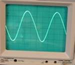
You can leave out the buffer(amplifier) section all together if
no higher output is needed and no low impedance load is applied.
The amplificated signal of Q2 is further cleaned up and adjusted for 50 Ohms by L2/L3,C11,C13,C14
The project can be fed with any voltage between 8 up to 15 volts, BUT, you need to set P2 so no more than 50mW (unmodulated is measured) which gives a total current around 40mA. Much more power would distort the modulated signal and probaly burn out T2.
AM
![]()
Amplitude
Modulation (AM) is a process in which the amplitude of a radio
frequency current is made to vary and modify by impressing an
audio frequency current on it.
This was the first type of modulation used for communicating
signals from one point to another and is still the simplest to
understand.
A radio frequency current has a constant amplitude in absence of
modulation and this constant amplitude RF carries no information,
i.e. no audio intelligence and is of no use to radio telephone
(voice communication), but has application in morse code
communication.
In its basic form, amplitude modulation produces a signal with
power concentrated at the carrier frequency and in two adjacent
sidebands. Each sideband is equal in bandwidth to that of the
modulating signal and is a mirror image of the other. Thus, most
of the power output by an AM transmitter is effectively wasted:
half the power is concentrated at the carrier frequency, which
carries no useful information (beyond the fact that a signal is
present); the remaining power is split between two identical
sidebands, only one of which is needed.
Filter
2 filters are used. One to get a clean sinusoidal signal and the
second stage which is coupled to the load through an impedance
matching circuitry (L2/L3,C11,C13,C14). Care is taken at this
stage so that no harmonic frequency is generated which will cause
interference in adjacent band (splatter) on other bands. This
3-element II-type narrow lowpass filter circuit for the desired
frequency cleans out any remaining harmonic signals very
efficiently. Remember: at this stage their are still harmonics
that could be useful for testing. The second harmonic will be at
2Mhz, third 3Mhz etc.
To prevent any other harmonic and leave only the fundamental
frequency, further filtering is required.
Modulator
Is done by Q1 (PNP BC328, 2N3906...). Audio information is
impressed upon the carrier frequency at this stage.
Collector modulation is applied here. Modulation depth can be
controled by changing P2 (be carefull not to exceed 50mW
unmodulated).
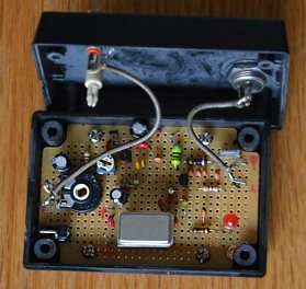
Housing/shielding
The whole circuit needs to be mounted in an
all-metal/aluminum case. If you're unable to obtain an all-metal
case, then use a roll of self-sticking aluminum tape (available
from your hardware store) or PVC box painted with graphite paint
or any conductive paint.
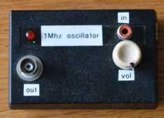
Specifications
Peak Design Frequency: 1MHz (schematic should work without any major changes between frequencies 800kHz...1200kHz)
Output RF PEP power: approx. 50mW (Can be set anything from 5mW to 50mW.)
AM modulated. Modulation depth can be set by changing P2
Output impedance 50 Ohms (buffer Q2 is used)
Band-pass type harmonic L-filter + low-pass PII filter
Usable voltages: Vcc 8 - 15 volts (and set to 40mA with P2)
Average current: I= +/-40mA
Xtal oscillator, 1MHz
LF input +/-
100mV @ 1K?????????
Schematic AM reference oscillator with modulator and rf amp/buffer: fig1
Parts list 1MHz AM oscillator/transmitter
Q1 2N3906, BC328 (PNP)
Q2 2N3904
IC Xtal Oscillator 1MHz
C1 = 10uF
C2 = 100n (poly)
C3 = 2.2 nF (polyester)
C4 = 10uF
C5 = 100n
C6 = 100nF
C7 = 4n7
C8 = 47uF
C9 = 2n2
C10 = 2n2
C11 = 56pF
C12 = 22nF
C13 = 4n7
C14 = 1n5
R1 1k8
R2 4k7
R3 18k
R4 18k
R5 470
R6 18
R7 1k
P1 5k (volume)
P2 is a trimmer to set the output power and modulation depth (5mW...50mW)
L1, L2 and L3= 10uH