
RE-PSF14A12D
revision 4
Four
types of Homebrew 12/20/30 Ampere 13,8volt power supplies:
RE PSF14A12D, PSF14A20D, PSF14A20 and PSF14A30
RE-PSF14A12D
revision 4
By Guy, de ON6MU
This is an easy to make power supply which has stable, clean and
protected output voltage. The overal dimensions can be kept
(relative) small by using TO220 darlington BDX-33 transistors.
Using 3 BDX-33 darlington transistors is almost 3 times the
amount of amps then the power supply delivers, making it real
though to brake ;). Although you could use this design to deliver
20 amps (with almost no modifications and with a proper transfo
and a huge heat sink with a fan), I did not needed such much
power. Second reason was the size of the alu box I happen to have
spare HI. There was simply not enough room for the transformer,
and surely not enough space to mount a huge heat sink, as the
BDX33 transistors can get very hot, and they do not like that so
much.
It is obvious, but I would like to mention that you could make
this power supply with less BDX-33 transistors if you do not need
high power.
Although the 7815
power regulator should kick in on shortcircuit, overload and
thermal overheating, I build in a very simple secondary
overvoltage protection that's made out of 12 volt relay. The
rectified voltage of: 15 volt x SQR2 = 15 x 1.41 = 21.15 volt
measured on C1. This is the voltage that could be on the output
if one of the transistors should blow. We need a little
calculation to get the exact voltage (or higher) to power the
12volt relay which should disconnect the output. In this example
we use for diode Zd 9v/5watt -> 21v - 9v = 12 volt. To allow
the relay to disconnect the output on lower voltages, use a lower
voltage for diode Zd. You could use a different voltage relay
too, but diode Zd should be calculated to allow the relay to work
just when the output voltage rises over 16 volt + (Zd in the
schematic).
Remember that the relay needs to be able to switch 12 amps (or
more). If the relay offers multiple switches then please use
them. The more the better (also less resistance hence voltage
drop when loaded).
P1 allows you to 'trim' the output voltage exactly to 13.8 volts.
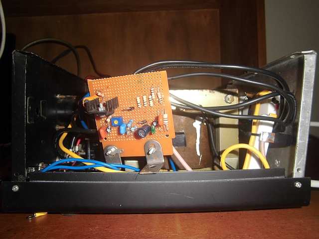
Remember to isolate the transistors from the chassis/radiator! This is very important! Use a radiator (heat sink) of appropriate size and surface area; insulating and heat-conducting spacer or at least a thin mica; hot adhesive and thermal paste. Use thick wires.
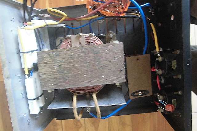
Just to be sure to prevent HF entering (or going back to the mains) use a ring core to turn the mains a few times around it (see insides pics).
Revision 3
. Zd was wrongly connected after the relay switch instead of
before
. C5 changed to 330uF to improve ripple rejection and
stabelisation
. primary side of the transformer added 250v/2n2 decoupling cap
. P1 = 500Ohms or 1k trimmer is sufficient
. reversed diode over IC1 removed
RE-PSF14A12 Power supply Schematic 1
Part
list PSF14A12D
12 Amp BDX33-based power supply:
2 x 15 volt 6+ amps
2 times two MR750 (MR7510) diodes (MR750 = 6 Ampere diode) or 2 times 3 1N5401 (1N5408) diodes.
F1 = 1,5 (2) Amp
F2 = 15 amp
R1 2k2 1 Watt
R2 10k
R3 1k 0.5 watt
R4,R5,R6,R7 0.1 ohm 5 watt
R8 4.7
R9 6k8
C1 two times 4700uF/35v
C2,C5 330uF/35v (revision 2: C5 = 330uF -> improved ripple rejection and stabelisation)
C0',C3,C4,C6,C10 100nF
C7 330uF/25v
C8 47nF
C9 47uF/25v
D1 1N5401
D2 LED
D4, D5 1N4001
IC1 78L15
relay 12 volt 2x5 amp switching
3 darlington transistors: T0,T1,T2 = BDX-33 NPN TO-220 transistor
Zd 8 or 9 volt, 5 watt
Zd2 15 volt, 5watt
P1 500 Ohm trimmer
If using a bridge rectifier (like in schematic 2) you do not need 2 x 15 volts 6 amps, but 1 x 15 volt 10+ Amps
Part
List PSF14A20D
20 Amp BDX33-based power supply:
2 x 15 volt 12+ amps
2 times 3 MR750 (MR7510) diodes (MR750 = 6 Ampere diode) or 2 times 5 1N5401 (1N5408) diodes.
F1 = 3,18 Amp
F2 = 25 amp
R1 2k2 1 Watt
R2 10k
R3 1k 0.5 watt
R4,R5,R6,R7 0.1 ohm 10 watt
R8 4.7
R9 6k8
C1 22000uF/35v
C2, C5 330uF/35v (revision 2: C5 = 330uF -> improved ripple rejection and stabelisation)
C0',C3,C4,C6,C10 100nF
C7 330uF/25v
C8 47nF
C9 47uF/25v
D1 1N5401
D2 LED
D4, D5 1N4001
IC1 7815
relay 12 volt 10 amp switching
Four darlington transistors: T0,T1,T2,T3 = BDX-33 NPN TO-220 transistor
Zd 8 or 9 volt, 5 watt (1N5346)
Zd2 15volt, 5watt (1N5352B)
P1 2k trimmer
If using a bridge rectifier (like in schematic 2) you do not need 2 x 15 volts 12 amps, but 1 x 15 volt 20 Amps
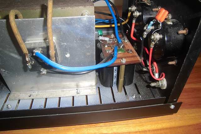
The power supply
insides
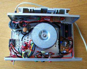
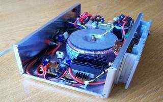
A
simple temperature controled fan:
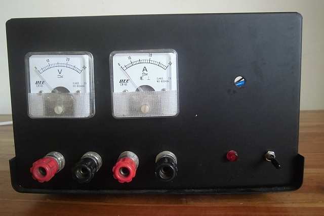
20/22 Ampere or 30/32 Ampere 13.8 volts
power supply
RE-PSF14A20 or PSF14A30
de ON6MU
RE-PSF14A20
Power Supply Schematic 2 (new design) revision 2014
Remember to isolate
the 2N3055 transistors from the chassis/radiator! This is very
important! Use a radiator (heat sink) of appropriate size and
surface area; insulating and heat-conducting spacer or at least a
thin mica; hot adhesive and thermal paste.
PSF14A20 Specs
Heavy duty power supply 13.8 volt, 20 or 30 amps continue
low ripple
short-circuit protection
HF-immunity
Voltage can be set between 12,3 and +/- 15 volts
only 0.35v drop at full load
parts widely available and calculated way over the maximum load
Of
interest
PSF14A20 Parts (30 amp version PSF14A30 in blue)
transformer capable of delivering 20 amps @ 15volt (30 amps)
4 x 2N3055
(6 x
2n3055) (you can
also use the 2N3773 transistor)
Use a large
radiator (heat sink) of appropriate size and surface
area; insulating and heat-conducting spacer or at least a
thin mica; hot adhesive and thermal paste.
IC 1: 7812 (small heatsink)
D1: MB2504
is used as it is a 25 ampere rectifier bridge and should
also be very good cooled.
Or you could use 3 times four BYW29 8 amp diodes (TO220
pinning, cooling).
D2 & D3: 1N4001 or simular
D4: 1N5401 or simular (1N5400...1N5408)
Zd: 15volt, 5watt (1N5352B) or a 15v 6 watt variant in the BZW03-Series
C1: 47nF
C2: 22000uF (+ 10000uF) 35volts
C3: 100uF/35volt
C4: 100nF
C5: 4.7uF/35volt
C6: 4.7uF/35volt
C7: 100nF
C8: 220nF
C9: 220uF/25volt
C10: 47nF
C11, C12: 100nF
R1: 2k2 / 1W
R2: 10 1/2W (2,2 1/2W)
R3: 6,8 1/2W (2,2 1/2W)
R4': 1 Ohm 1/2W
R5': 0.1 Ohm/5W
R6: 2k2
R7: 10
R8: 2k2
R9: 22
R10: 1k5
R11: 10
R12: 220
P1: 1k
P2: 2k2 trimmer (to calibrate the meter that will be used to measure the amps)
F1: 2A (3.18A)
F2: 22A (35A)
P1 allows you to
'trim' the output voltage exactly to 13.8 volts.
Just to be sure to prevent HF entering through the mains use a
ring core and turn the mains a few times around it (see insides
pics).
Be sure to use thick braid wires!!! They need to handle 20 (30) amps continues!
Total
revision changes:
. highly improved voltage stabilisation
. output voltage feedback circuit stabilisation
. BDX-33 removed
. Cap after 7815 changed from 1uF to 4.7uF
. Resistors before the input of the 7815 changed
. reverse diode (between collector and emittor of 2n3055) removed
. voltage can be set exactly to 13.8v (P1)
. minor HF-immunity changes
. reversed diode over IC1 removed
Revision 2016:
. R10 changed 1k5, and P1 to 1k (thanks Goran 9A6C)
Goran reported that he
could not reach 13.8 volts using a 500 Ohm potentiometer(P1)
parallel with the 1k resistor(R10).
Replacing P1 & R10 with fixed resistor of 680 Ohm would give
approx. 13.6 volts.
Revision 2017:
. added ampere meter without using the meter in series (P2
trimmer to calibrate the meter that will be used to measure the
amps)
A crowbar circuit is an electrical circuit used to prevent an overvoltage condition of a power supply unit from damaging the circuits attached to the power supply. It operates by putting a short circuit or low resistance path across the voltage output (Vo), much as if one were to drop a crowbar across the output terminals of the power supply. Crowbar circuits are frequently implemented using a thyristor, TRIAC, trisil or thyratron as the shorting device. Once triggered, they depend on the current-limiting circuitry of the power supply or, if that fails, the blowing of the line fuse or tripping the circuit breaker.
Pictures
of people who made the PS
This is how Dan, YD1BWB made it:
![]()
click on the images to enlarge
Thanks Dan!
Links of
interest:
.ON6MU
Homebrew projects
.Radioamateur related projects
.ON6MU
78h05_powersupply
.Versatile 7805 based 5Amp powersupply
Home
www.qsl.net/on6mu
![]()