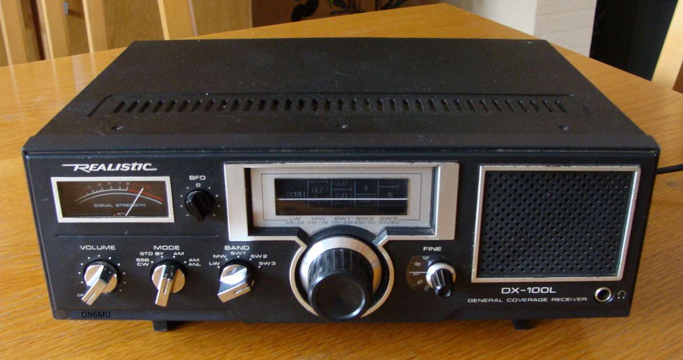
Realistic
DX-100L Receiver
(model20-9228
- Belgian FCC approval number: RTT/ONL/X0031)
| DX-100L radio details | |
| General Coverage Communications Receiver | Rating (1-5): H (1) |
| Made In: Taiwan? 1981-1984 (27 may 1981) | Voltages:12VDC 4W - 117/220 VAC 6,5W |
| Coverage: 150-30000 kHz (All HF bands) | Readout: Analog |
| Modes: AM/SSB-CW | Selectivity: One Position |
| Circuit: Single Conversion | Physical:12x5.7x8" 10 Lbs. - 30x22x11 cm |
| Features:
¼" Head. Jack, S-Meter, ANL, Dial Lamp,
Standby, Fine Tuning, Longwire antenna connection, Telescopic antenna. |
|
| New Price: $100 | |
| Comments:
The DX-100 also operates from 12 VDC. A basic receiver.
Please note that Realistic is a registered trademark of
Tandy Corporation. Note: There is also a DX-100 version without longwave reception: Important: the components numbers doesn't match on the schematics of both versions |
|
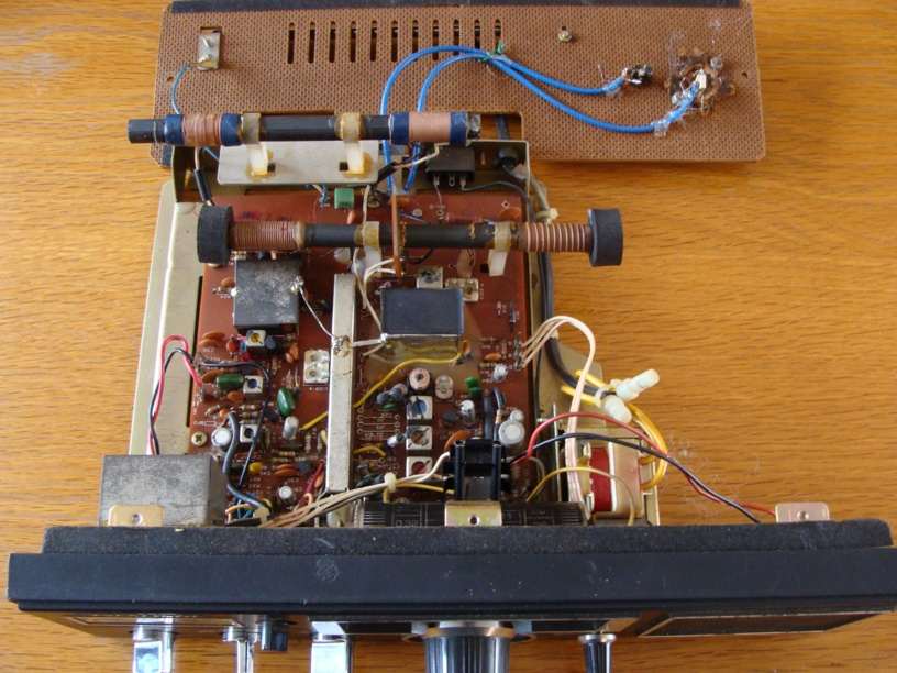
DX-100L
MODS (de ON6MU)
Place take caution when performing
these modifications.
I can not be held responsible for any damage or loss of waranty
leading from opening your receiver and performing any
modifications.
Use them at your own risk.
Remember: there are some schematic differences and some changed
part numbers between DX-100 and DX-100L!
Improved
(bass) audio quality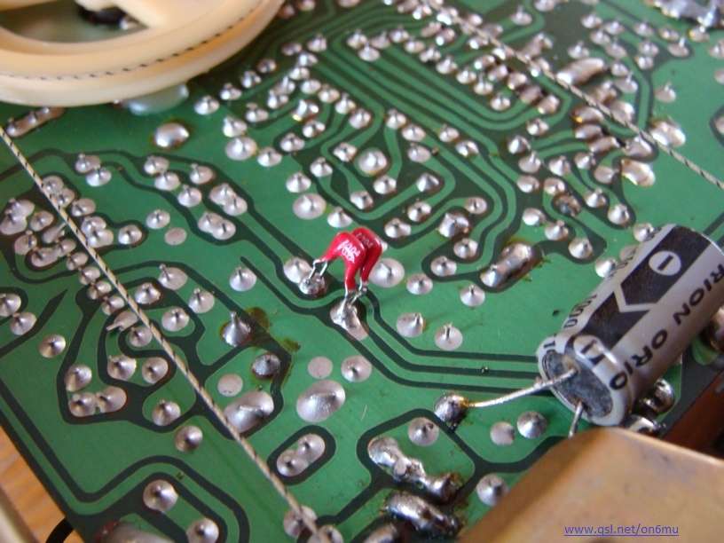 fig.01 fig.01 |
|
Improved
BFO SSB detection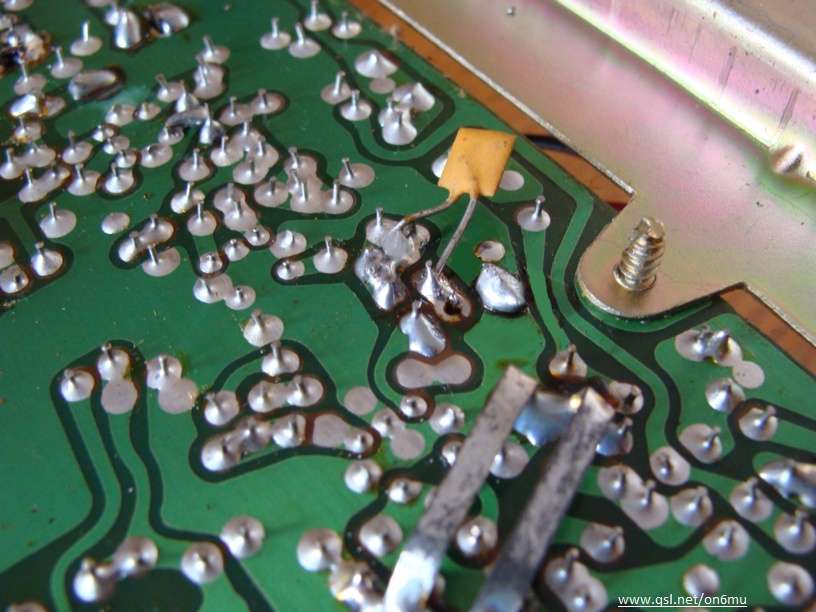 fig.02 fig.02 |
|
Improved
VFO drift stability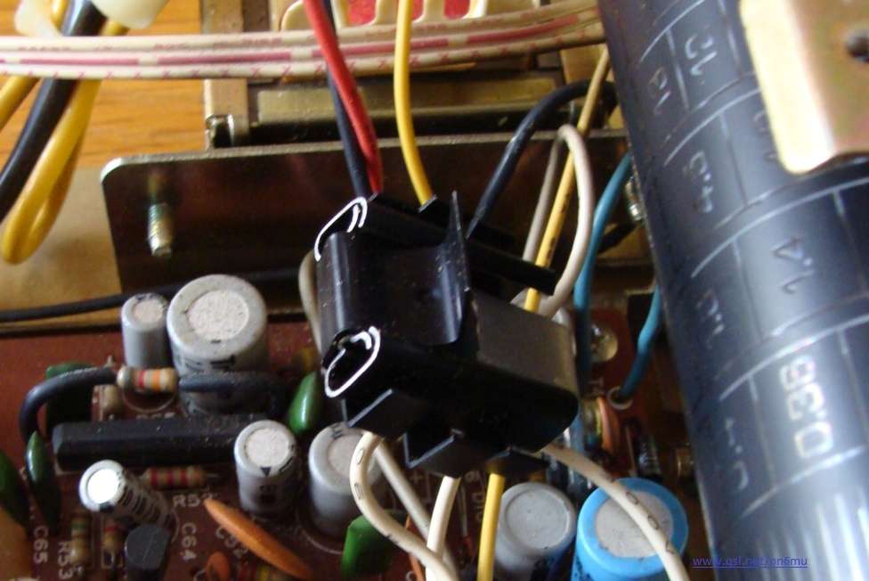 fig.03 fig.03 |
|
Connect
a Frequency Counter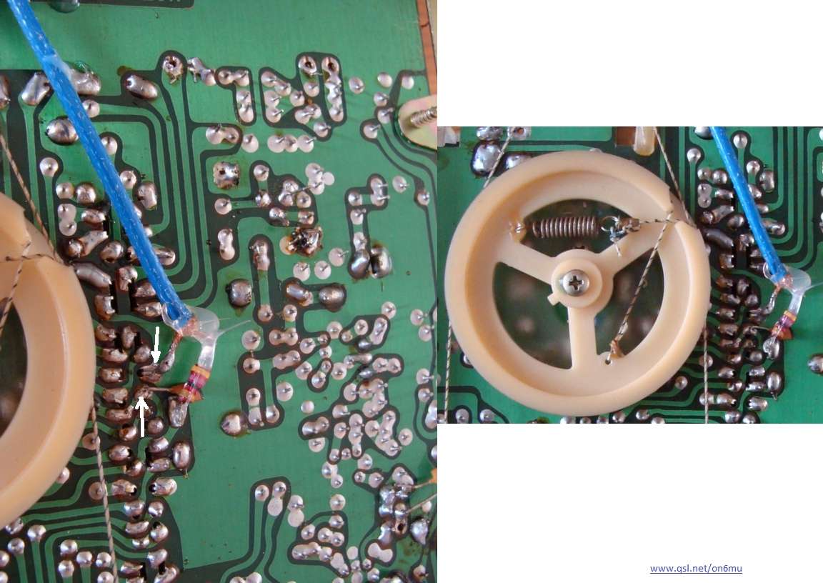 fig.04 fig.04
|
|
Connect
a 50 Ohm coaxial Antenna fig.05 fig.05 |
|
 fig.06 fig.06 |
<- This is how I lead the 50 Ohm antenna connection and the frequency counter connection to the outside world (fig.06). Lots of space to mount the extra connectors there. |
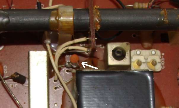 fig.09 |
|
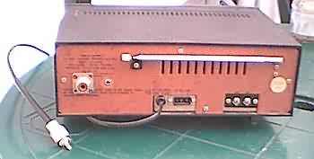 fig.07 fig.07 |
|
| Fine tuning SSB mod from Andy KA1GTT |
|
|
DX-100L: My very first "real" world receiver. Enjoy this little old radio!
The youtube made by
David shows an example of some of my mods done by David:
http://www.youtube.com/watch?v=29p_OvircsQ
and http://www.youtube.com/watch?v=Tw3UpUx3EiY
 SO239 backside