Converting
the Spectrian SCPA1063W amplifier on
13cm (2320Mhz)
DISCLAIMER: THESE REMARKS AND
DESCRIPTIONS ARE PROVIDED FOR INFORMATION ONLY. THIS AMPLIIFER IS A
HIGH POWERED MICROWAVE DEVICE. THE AMOUNT OF AVAILABLE RADIATION WILL
CAUSE HARM IF APPLIED WITHOUT CAUTION
Here is my take at converting the Spectrian to 2320MHz, the European
13cm band. I know a lot is on the web (thanks NR6CA), but I also
found a lot of stuff not 100% same in my case. This document assumes
you have read everything that is on the web regarding this amp, it is
just a collection of additional remarks.
- The DC/DC board
is a monster... even though it can generate the 12V we need for the
driver board, I got rid of it. Strange noise and crackles, buzzes....
and very low efficiency.
- So one just
connects externally provided 12V and 26V to the connectors marked on
the power distribution board.
- For the three
boards in parallel, I never found 18dB gain as claimed. More like 13 or
14dB....maybe my amp was a lemon.
- But... not to
worry, it just means applying a bit more drive, like 10W for 200W
output....
- I measured the
following in/out for the finals combined: 1/20 5/100 10/200 at
(18A/27.2V, efficiency seems high?) and then 30/450 for a few seconds
before the power supply quit.
- So in order to
drive this amplifier from a DB6NT (1-1.4W) we need to come up with an
intermediate amplifier. We can use the existing driver board for that.
- As per manual
(see below), pin 9 of the driver board should be enable. This did not
work for me. I had to hard-wire the FET gate to 26V, this turns on 12V
for all the stages.... 30-35dB gain....
- A trimmer
port on the driver board can be used to set the gain of the whole setup
- I use 10mW in for 200W out.... a pretty decent piece of machinery
this amp, a marvel of overengineering maybe?
Pictures that may be of some use:
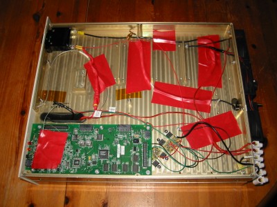
The first picture shows the bottom compartiment, all boards except the
digital controller removed. I just use the LEDs of the board, to
indicate 26V, 12V and PA enable. 2 DB6NT sequencers are used, one for
driver enable (26V) and antenna relay out (to GND), the other one for
main PA
enable (12V). I run the sample out connector to the driver input,
and terminate the sampling line in 50ohms at this side to avoid
trouble. Use a piece of semi rigid with attached MCX from the discarded
original I/O connector.
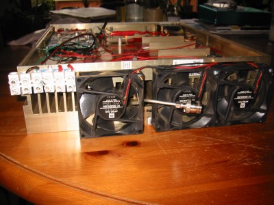
Added homebrew I/O connector as well as three fans. We are dissipating
+/- 500W
of heat here. I dont like the SMA semi-rigid output line, but did not
have
space left at the back.
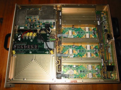
The first RF board (channel selection? modulation?) has been removed,
but power distribution and driver board remain used.
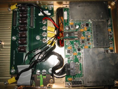
Close up of power distribution and driver.
Note:
- the green wire
on the FET gate of the driver enabling 12V to all
transitors on the driver board by applying 26V.
- the new black
wires on the power distribution running from pins 7
12 17 of the 26 pin connector, these enable the amp finals by applying
12V.
- the driver
gain pot to the left of the "middle stage" on the
driver. This allows setting for exactly 200W out at +/- 10mW in. Go
higher at your own risk.
Here is some info on
the driver I found on a German site, likely copied form Ebay:
"This is for one very linear Class A RF amplifier which is removed from
a new Spectrian high power Amp where it was used for driver for the
main PA boards. Output power is 15W without any compression from
2.30GHz to 2.40GHz with a linear gain of 35dB. Great amplifier for ATV
or SSB use. This amplifier is also useful from down to 2.2GHz and up to
2.5GHz with a power output of 10W and a gain of 30dB. Power requirement
is 12-14V @ 10A and + 24 to +28v bias @ 50Ma. This bias is used for the
gate voltage circuit on the power control *FET*. This is easily
obtained using a small DC-DC converter (12vin and 12-15V out and
putting its output in series with the 12v supply. There is a logic
level enable pin which requires grounding to enable power to this
amplifier and can be used for a PTT/KEY control. The connector also has
a direct temperature output pin with the function 10.0mV/degree F which
measures the board temperature close to the 30W RF output GaAs *FET*
(*NEC **S2527*-30). Note that the output of this amplifier is protected
by an internal 125W isolator! Here are the pin functions for the DC
bias connector: Pins 1,2,3,4 are all +12 to 13Vdc @ 7.5 or so amps.
Pins 5,6,7,8,10 are all ground. Pins 12,13 are N.C. Pin 11 is Logic
level Low enable, normally floats high. This turns on the +12v to the
internal transistors. Pin 14 is + 26V bias supply input @ 50Ma. Pin 9
indicates temperature = 10mV/degree F. This board comes mounted on a
1/4 inch thick aluminum heat spreader which has 6 mounting holes for
mounting to a heat-sink."
As described
above I had to enable the amp differently, but the info is useful
nevertheless.
Have fun on 13cm, the forgotten
microwave band... one cannot say power isn t cheap!
Email [email protected]
-
in case of problems with the qsl.net address, please use [email protected]
back