|
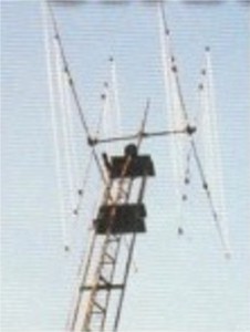
This is a picture of My home-made quad-antenna system. The boom-length is 2.5 meters (about 8.2 feet) and I used aluminum spreaders, insulated from the boom with heavy-wall PVC piping in the boom-clamps. Each horizontal spreader is in two sections with a 20cm ( 8") insulator in the middle to prevent (too much) interaction between the loops and spreaders.
The reason why I used aluminum spreaders is that they are very strong, much cheaper than fibre-glass and I just wanted to try it. The diamond shaped loops are in this case mechanicaly better because the vertical spreader can support the gamma-matching system.
The loops are made out of 1.5 square mm PVC-coated Litze-wire and they are insulated from the aluminum spreaders.
The three loops are in resonance with the aid of a noise-bridge and a Stabo RF-analyzer (Autek RF-1 in the USA). The best method is to tune the loops Yourself because I have quite a few antenna-books, but all with different loop-measurements. Maybe it is because of the aluminum spreaders and wire type but My loop -measurements are also different to the ones in the books.
First I used a tri-gamma matching-system with a compensating-cap to feed the antenna with one feed-line. This did'nt work out very well. Only two bands were working okay with a bad front to back on two bands. When I replaced the RG 213 coax-cable with 1/2 inch coax, two years ago, it was time to build a relay switch-box and feed the loops seperately from the switch-box to the loops with RG 213. I could have used 1/4 wave coax transforma - tion but had the gamma-matching system. Each loop starts with 9mm aluminum tubing and after a certain length (depending on the band and length of the gamma-match) the loop continues with the Litze-wire. The gamma-match rod (also 9mm tube) is parallel with the 9mm tube and the capacitor is formed by the coax (PVC and outer-braid stripped), pushed in the gamma tube. So the Litze-wire does'nt need stripping and no water gets into the tuning section.
My free-standing tower is 21 meters (69 feet) high and I've built a elevator-system to crank the antenna or lower it. There is a pulley on top and a winch at the bottom with a stainless-steel cable over it. The antenna and rotator are mounted on a frame with the cable attached to it.. The frame has got rollers that roll in U-shaped steel guides to the top. When lowered, in case of strong wind or antenna-work, the antenna will stay in horizontal position. This is very practical to work on.
A FEW OBSERVATIONS;
With the antenna-spreaders touching the ground, it is still possible to work DX but only towards the West or East. (The antenna can't be turned when lowered) I tried this with My Yagi but it was not possible, only warming the sky. There is a shortening-effect of the loops for a tri-band quad, compared with a mono-band quad. Bringing the loops closer to each-other or further apart will change the reactance. When cranking the antenna up, I measured the antennas reactance every meter (with the analyzer and a coax-cable with a neutral electrical length ) and saw the reactance go up and back to normal accordingly to the hight of the antenna at that moment. So antenna hight does play a roll in reactance and also tuning.
The antenna is up since March 1998 and I worked 287 DXCC prefixes with normal power.
![]()
![]()

This page is
created by ON4CFZ on 01-03-2001 with the aid of![]()
Best viewed with ![]() JAVA supported.
JAVA supported.