ON4AEY’s Radio Amateur site
 

HamClock by WB0OEW

After the publication of this project in the ARRL’s QST magazine I was direct interested to add this also to my shack. Starting the project from Elwoods article.  On his website you can find all information about his project: http://www.clearskyinstitute.com/ham/HamClock
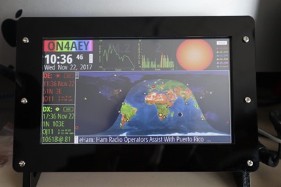
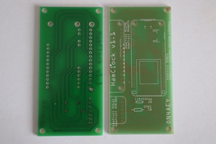
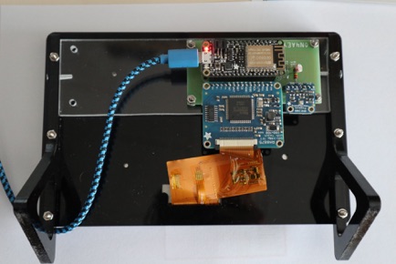
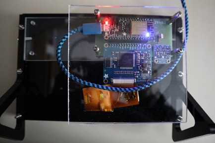
My result:

The tweaks I made:

I use another cabinet than the one used in the QST article, found his one on the internet @
https://nl.aliexpress.com/item/7-inch-LCD-Display-Screen-Bracket-Holder-Case-for-Raspberry-Pi-3-Acrylic-Bracket-Support-for/32825698598.html?spm=a2g0s.9042311.0.0.evUiEM
this one looked like it needed less adaptation than the one in the article, and indeed. The front frame needs no adaptation. The second frame which holds around the screen also no adaptations needed you need to make sure the display is placed as much as possible to the right here . The third frame needs to fit around the TFT unit and so some rework is needed to make the hole in the frame bigger, so some file work is needed. The back frame again needs no adaptation.

Then I created a small PCB because I didn’t want to fiddle around with wires.
the resulting PCB:

If interested in a PCB you can contact me via email to check on availability. A future improvement on the PCB will be correcting the mentioned value of the resistor near the photocell, and adding the resistors for the long wire connections to the weather module.

And now the back of the clock looks like:

You can see my PCB mounted with four 3mm screws to a 5mm thick plexiglass which is made to fit between the 2 legs of the cabinet, 2 small screws fit this to the cabinet. Yep you have to drill small holes for this. The idea is to put another piece of plexiglass above the electronics, the final back photo:

I’ve found this a nice project to make, and like to thank Elwood for the initial article that made me go!