Change of potentiometer linearityFebruary 2019 Problem definitionVoltage regulation using linear potentiometer is not in all occasions optimal. For example in case of laboratory power supply maximum output current potentiometer area of small current values is really a small part of the scale. Problem can be solved using potentiometer with nonlinear characteristic (logarithmic). Potentiometers of that kind can be found on the marked, but also with linear potentiometer there are a good possibilities. AnalysisThere is a possibility to modify linear potentiometer to that one similar to logarithmic or exponential using additional resistor. Depending on the location where it is added the result is similar to logarithmic or exponential. That means scale is expanded in the lower or the upper part.

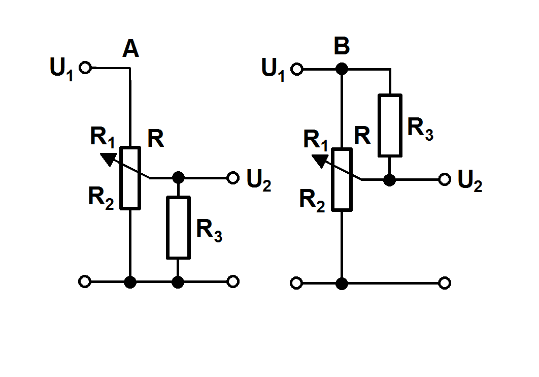
Additional resistor can be added or between middle and lower end (case A) or middle and upper end of potentiometer (case B). Depending on value of added resistor comparing to potentiometer resistance it results in more or less significant change. In general the smaller the resistor the bigger the change. For the purpose of problem analysis there will be introduced so called "normalisation":
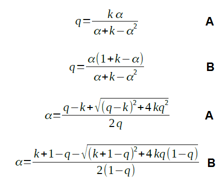
Using those substitutions one can derive equations shown below. They are showing both dependency of angle on division ratio as well as opposite - division ratio as dependency on angle.

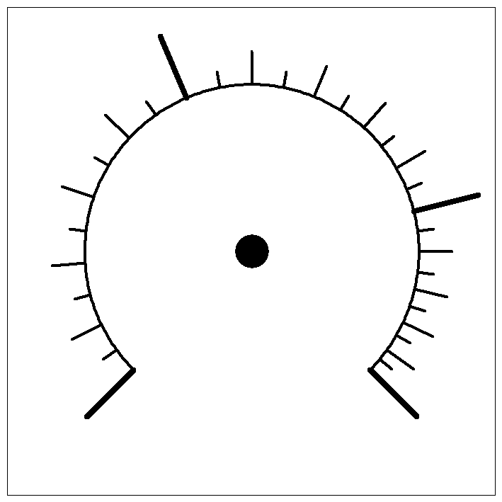
The equations may look difficult, but they can be easily handled using spreadsheet program (for example MS Excel, LibreOffice Calc or so) and in result definition file for scaler program can be prepared. GraphsUsing spreadsheet processor series of calculations were performed for case A and B and k equal 0.1, 0.33, 1 and 3.3 (R3 as multiplication of R). As it can be seen R3 having tenth value of R has very strong influence on potentiometer angle/division ratio. Even 1/3 of R is still very visible. Scale example shown below was calculated for the case A and R3 = R (k = 1).

Scale example

SummaryUsing procedure described in this contribution it is possible to modify linear potentiometer characteristic to be similar to logarithmic or exponential. Equations shown above allow calculation of potentiometer scale parameters depending on requirements. A few details at the end - definition file for example scale was prepared as follows:
|