|
SL-9950 USB sound card solution ContentsPrefaceThere is mini USB sound card - Speed Link SL-8850 - which I found to be very easily adopted.
Fig. 1: SL-8850 view. This gadget is slowly disappearing from market, but I hope it will have replacement or upgrade. Core of the device is C-Media chip CM-108. Chip data sheet is also available. Selected technical parameters of the CM-108:
Results of analysisI've analyzed, with a good magnifying glass and ohmmeter, schematics of the CM-108 and PCB of the SL-8850. I found very good correlation. To be exact - real board is using exactly the same components labelling, some components are, however, missing due to reduced functionality required for headset design. Original SL-8850 schematics (only important part):
Fig. 2: Original SL-8850 schematics Microphone input is done the standard way. Earphones output is a bit unusual - there are no electrolytic condensers - special pin of chip is used instead - "LOBS" - "DC 2.25V Output for Line Out Bias" (pin 31). It was found, that microphone input on pin 27 - "MICIN" - accepts DC input and it requires 2.2V DC to get zero output DC. Possibility of DC input solutionTo apply OpAmp solution described in the original project would require to add some additional components. The main problem, however, is feeding - there is no negative power -5V available on USB socket (and it is not easy to get it from notebook without braking in...). New idea is to change DC bias of "ground" instead of touching input:
Fig. 3: DC bias of "ground". It seems simple to get adjustable DC stabiliser chip (LM317LZ, for example) and create DC-shifted ground. But detailed view on CM108 schematics is showing, that everything is already in!
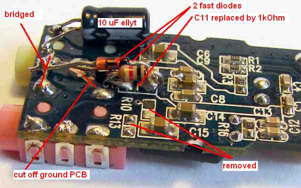
Fig. 4: Modified CM108 schematics. Required DC-shift is available on pin 31. It is used as common point of earphones. As a conclusion, there is no need for external components at all! Yes, there are some new components - resistor 1k and some 2 fast switching diodes to protect chip input... And electrolytic condenser to make dirty hack a bit cleaner. But all added components are optional. It may work also without them. ResultWhat is needed:
Fig. 5: SL-8850 modifications. It works fine. With the device I did a few measurements. I found that maximum sensitivity is approximately +/- 120 mV without microphone boost. Microphone boost is +20bB (10x), which means +/- 12 mV! This seems too much for practical purposes... This was not tested. Normal operation requires, however, switch off microphone boost in MS Windows sound settings. ProgramFor this device original program was modified. It is using soundscope.ini file to store program parameters. Contents of the soundscope.ini file:
      [Program]
      Debug=1
      [Devices]
      Device Name = C-Media USB Headphone Set
      LineIn Name = Microphone
      ADBites     = 16
      [Calibration]
      Zero left   = 95
      Zero right  = 95
      MaxLevel    = 30480
      MaxVoltage  = 0,117
      [Range1]
      LabelL      = '0.2V'
      LabelR      = '0.2V'
      CalFactorR  = 1
      CalFactorL  = 1
      [Range2]
      LabelL      = '1V'
      LabelR      = '1V'
      CalFactorR  = 1
      CalFactorL  = 1
      [Range3]
      LabelL      = '4V'
      LabelR      = '4V'
      CalFactorR  = 1
      CalFactorL  = 1
      [Range4]
      LabelL      = '20V'
      LabelR      = '20V'
      CalFactorR  = 1
      CalFactorL  = 1
[Program] section contains only one parameter - "Debug". 1 means program writes debugging information into textual log file - log.txt. 0 means no debugging information. Default value should be 0. [Devices] section contains following parameters:
[Calibration] section contains basic parameters of measurement:
[Range1] - to 4 - definitions of 4 measuring ranges:
In this version of program it is fully configurable measurement ranges labels. CalibrationAspects of calibration described in original project are all valid. To make it as easy as possible the philosophy of calibration in this version of program was changed principally. Before starting change display mode to display raw data by clicking "Calibrated" button. Its label will change to "Raw data". Calibration has following steps: First is zero level calibration. It requires disconnect any external voltages from inputs and shortening both with ground. If using microphone input you should switch microphone boost function off. Display will show some values in both channells. Write them to the soundscope.ini file as Zero left and Zero right values. Second is measuring basic device sensitivity - connect variable voltage source and set DC voltage to get level line on the screen to be identical with 3rd one (over red line). Write value of channels as MaxLevel and corresponding voltage as MaxVoltage. Before calibrating voltage ranges switch back to "Calibrated" display mode. Third is to calibrate voltage ranges. It is expected to have range switch ready. Select first range both on screen and on switch. Using regulated power source apply appropriate DC voltage to the device - close to the 3rd line again. Display will show some voltage, which will be probably slightly different from real one. Calculate correction factors for both channels and write them to the soundscope.ini file as CalFactorR and CalFactorL respectively of selected [Range(1..4)] section. Example (channel L assumed):
Displayed voltage: 190 mV When writting CalFactorL and CalFactorR into soundscope.ini file be careful to use decimal separator "," or "." according your national settings. Repeat the procedure for all 4 ranges. At the end verify new values of CalFactors, recalculate them if needed. Note, that INI file is read only at program startup. So after each change in the soundscope.ini you have to restart program. RemarksFact, that measurement ground and computer ground are not identical must be taken into consideration. If measuring with computer connected to power socket on device connected to the power socket results are unpredictable. Damage of SL-8850 is highly probable. It is required to run computer in batery mode if measurements are performed on devices connected to power socket. When doing measurements on devices fed from bateries it is safe to have computer powered normally. Disclaimer We don't feel any responsibility for any damage of measuring or measured device or computer due to use of this design. |