Luigi's contribution
Luigi,, sent me recently his contribution - he added many new functions.
Very nice design. This is his article - translated by Gogle to English:
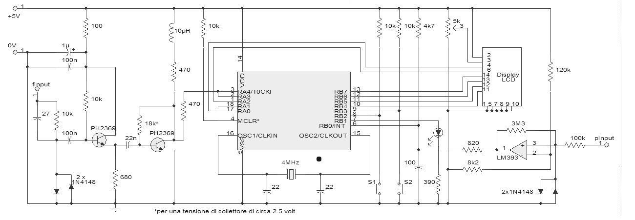
This is another reworking of the frequency meter of Peter Halicky (OM3CPH), already reviewed by Renato, to have four gates available (RB0, RB1, RB2 and RB3) to enter the period meter and switch between various functions.
As you can see on the schematics I also added an input preamplifier to increase the frequency input impedance not to overload the device under test. As input for the period meter, again do not overload the device under test, I used half LM393 which seems fast enough for measurements in microseconds.
Measurement of time is possible for the period, the positive and negative half period with the resolution in microseconds (max 16.777215 sec) and milliseconds (max 4h 39m 37.215 sec). LED connected to RB1 shows that PIC began measurement and goes off when completed.
With button connected to RB2 you can choose from following functions:
- frequency
- period in microseconds
- period in milliseconds
- positive half period in microseconds
- positive half period in milliseconds
- negative half period in microseconds
- negative half period in milliseconds
With button connected to RB3 you can start selected function.
Schematics

Frequency measurement program I modified to eliminate unnecessary zeros and automatic switch between MHz and kHz.
My program uses a display 2 x 16 characters, but changing the lines 593, 1025 and 1061 by value <10000000b> to always show in one line.
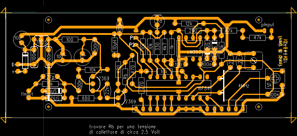
PCB

Image of the PCB is not to scale but users of PCB123 program can use available file, actual size is 101 x 37.5 mm. For more information e-mail Luigi.