|
What QRP Junior is? My idea was to prepare for beginners and for QRP traffic transceivers, a transmitter affordable enough for portable use. I respect that a highly advanced kit made up of sophisticated components and assembly designed to measure, a normal HAM may not have available. Having seen the design and workings of transceiver DOB80 by VK2DOB from Alex, OM3TY and since I have built direct conversion radios before, I liked it at the same moment. It has enough gain and is simple to make it work on other bands than 80meters. First prototype thus is made for 7MHz and here I've been testing crossmodulation from profesional AM radiostations. Later I made several changes. I used internal oscilator of one of SA612 and with varicaps I tune it in full size of amateur band. I included an electronic RIT and different type of phase shift of the oscilator signal. The transmitter has symetrical power amplifier, giving up to 2W on 50-Ohms in the antenna. Finally I add HF selective and tuned preamplifier to lower unwanted emmitions. First prototype of this transceiver I built on PCB size 165 x 85mm with the SMD technology. On the board are placed all components, all except the power plug. The box is made from two sheet metal parts, cut to size and bent. The board is attached to lower box by six self tapping screws. The upper box covers all parts from the top side and is secured by four screws. The main tune pot has 1:13 mechanical conversion gear to make tuning simple. The QRP Junior transceiver is available as a Kit, or you can build it on your own from documentation which is shown futher down. In the first case all SMD components for the board are assembled, with winding of coils, chokes and wire components and its preparation and assembly remaining for HAMs. All mechanical parts are cut and bent with pre-printed panel and scale. It offers the HAM about 40hours to put it together and make it operational. Version for different frequency band differs just in coils and some capacitors. Schematics For the QRP Junior schematic in the pdf format click here. This shown version is MARK I - one of advanced, but still is going to be changed. Please take it as an informal drawing for now. Look at the PCB with SMD components.
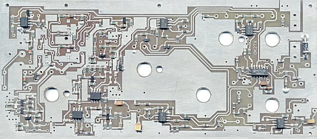
On this picture you can see a prototype board of QRP Junior on the double sided PCB, just without plated holes. Final version has printed silkscreen mask.
Power transistors are SMD too and are soldered on the opposite site. Empty holes are for pots, coils, wires and other non SMD parts, which are expected to be soldered in. |