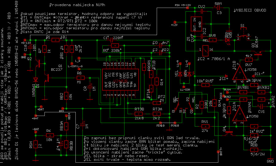
To MENU
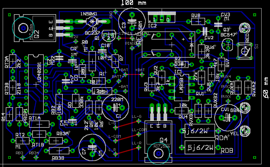
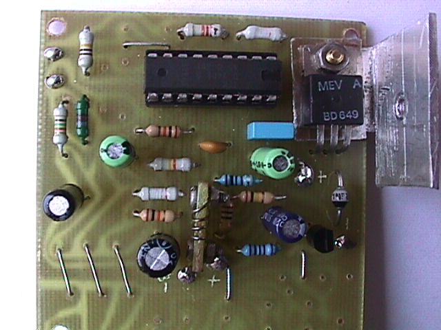
Printed circut board "hand drawn" :)

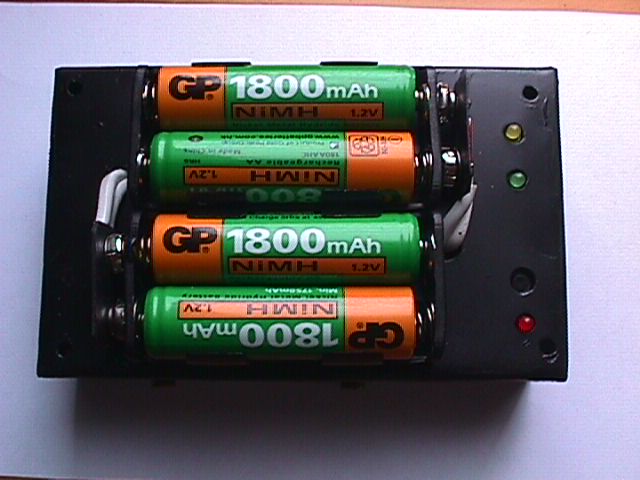
Charger part view
Discharger part view

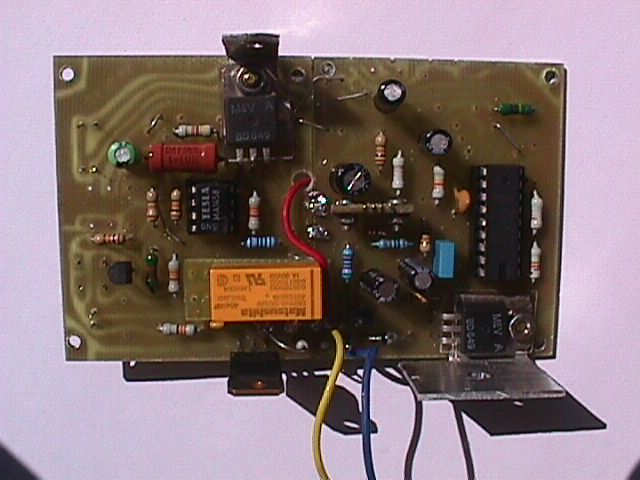
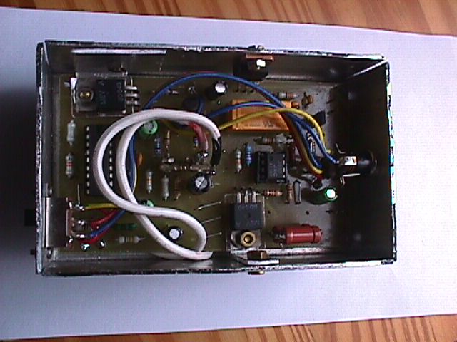
View of all circuit

Case top view
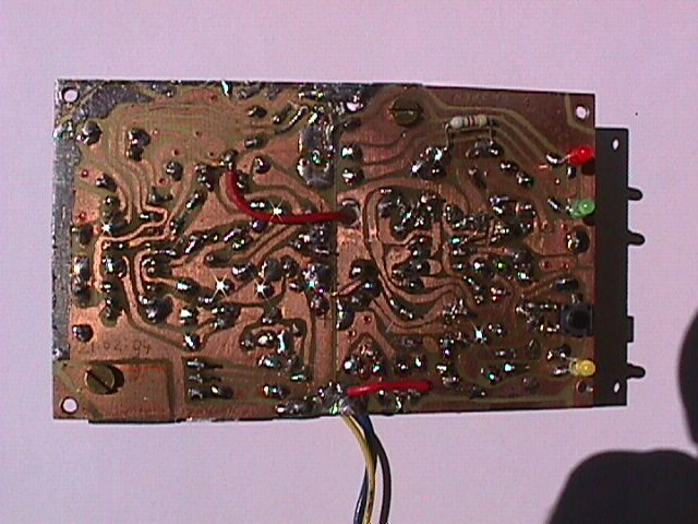
View inside the case from bottom
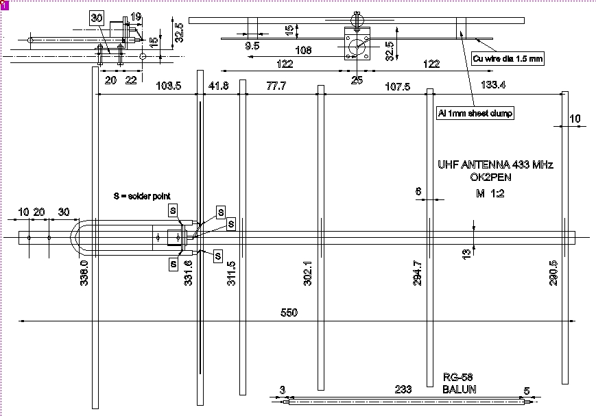
70cm UHF Mini Yagi antenna
To Main MENU
Below there is one description of my mini yagi UHF 430-440 MHz Yagi antenna. The center
frequency is 434 MHz. The antenna is used for packet radio on that band and has
the gain of about 13 dB. The antenna is pretty directional (horizontal angle +/- 10 degrees) and
with good polarization surpression. If you will built it, please make exact dimmensions
as shown on the drawing. The decimals of mm can be omitted.
ANTENNA DRAWING
To MENU
 DRIVEN ELEMENT
To MENU
DRIVEN ELEMENT
To MENU
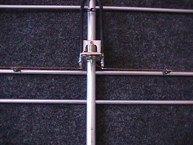
View of driven element with matching wires
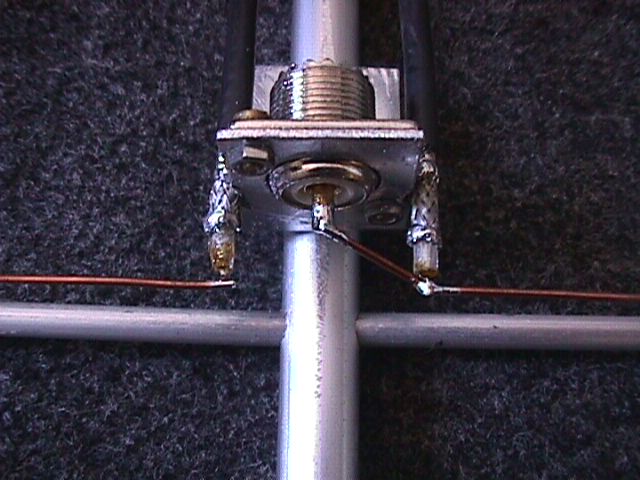
SYMETRIZATION BALUN
To MENU
Symetrization balun from a piece of RG-58 full shield coax cable
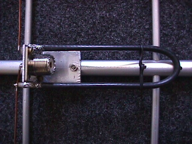
FEED DETAIL 1
To MENU
Driven element feeding assembly in detail 1
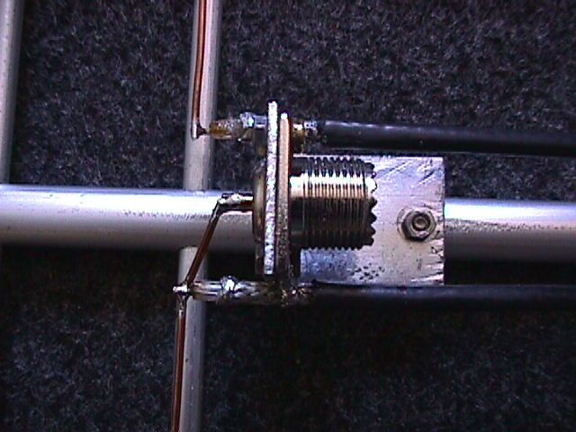
FEED DETAIL 2
To MENU
Driven element feeding assembly in detail 2
OVERALL VIEW
To MENU
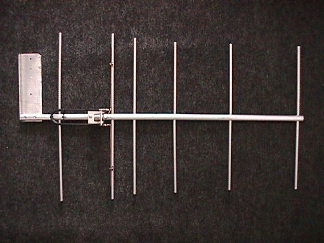
Overall view of the antenna. It's only 55 cm long.
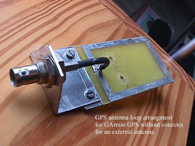
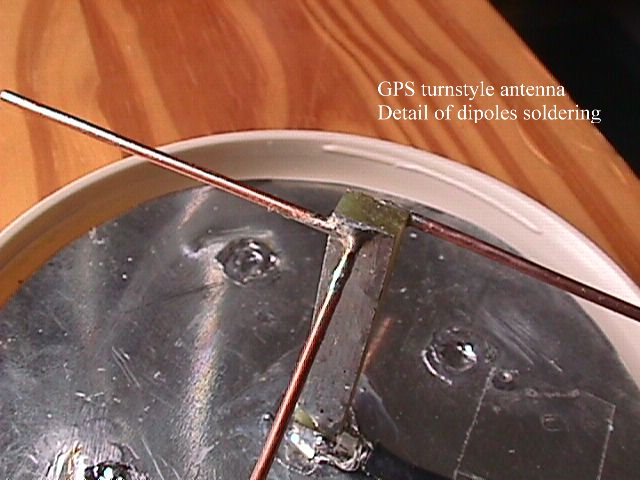
GPS external antena and coupling
to the GARMIN GPS receiver
To Main MENU
Below fotos of GPS turn-style miniantena and its coupling to GARMIN GPS receiver which
has no any connector for external antenna. Also shown DB-9 adaper to output GPS pins.
The pins are +3V RXD TXD and GROUND. Placing the antenna under the front window of the car
I receive minimum 7-9 satellites in one moment depending on surrounding country side.
Connector adapter - top view
To MENU
 Connector adapter - bottom view
To MENU
Connector adapter - bottom view
To MENU

Antenna coupler with BNC connetor
To MENU
Antenna coupler mounted
To MENU

Driven element feeding assembly in detail 1
Antenna detail - coax connection
To MENU

Antenna detail - elements
To MENU
Antenna view from side
To MENU

Antenna overall view
To MENU

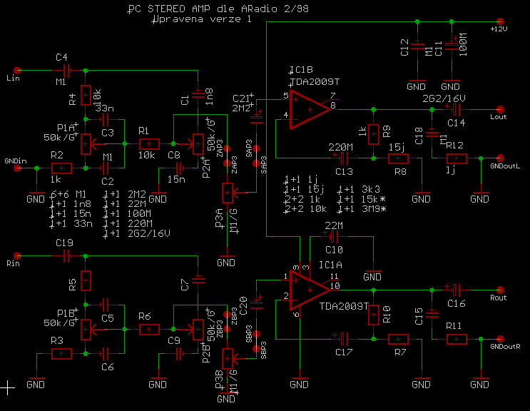
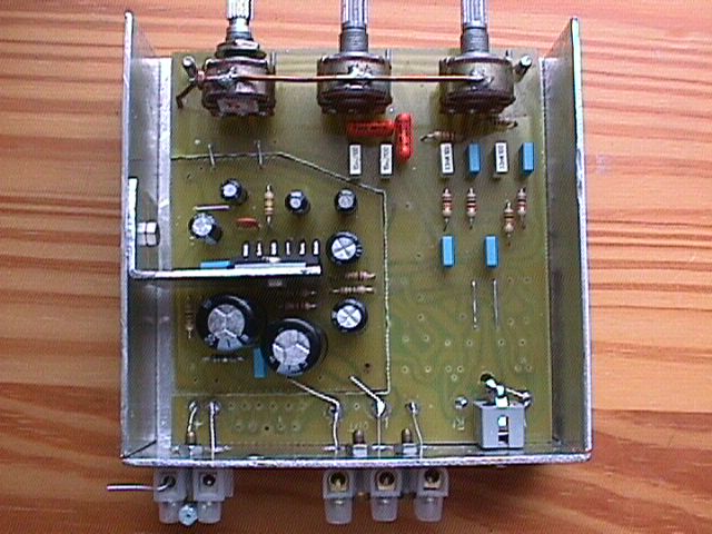
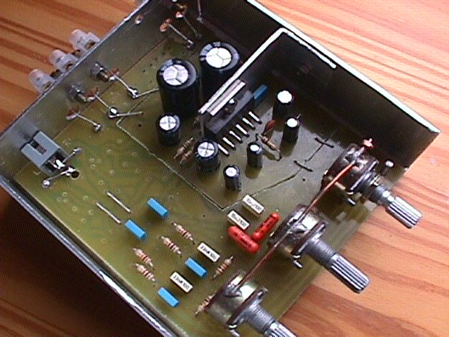
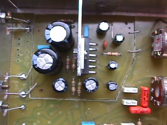
Audio amplifier with TDA2009A
To Main MENU
Below here is the description of my stereo audio amplifier using the chip TDA2009A.
This amplifier must have both speakers connected otherwise it is drawing high current
more then 1 A. Although the chip has the temperature protection inside it is not recommended
to switch the circuit without both speakers connected.
With the input signal the supply current at 12 Volts can reach upto 5 Ampers so good
12V/5 Amper power supply is needed. It can be supplied from the switched AT pc supply as well.
That's why also good radiator to be mounted to the amp case (not shown on photos).
SCHEMATIC DIAGRAM
To MENU
 View 1
To MENU
View 1
To MENU
View 1
To MENU
View 1
To MENU
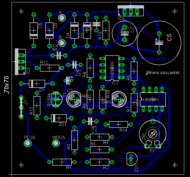
CAR HERMETIC BATTERY CHARGER
To Main MENU
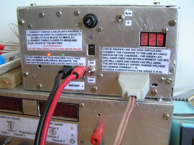
Below is the description and photos of the automatic car hermetic battery charger.
The charger is charging in mode of constant current of about 1 Amper. There is LM350
voltage regulator working as constant current supply. The charging process is fully
automatic. When the charge voltage reaches about 13.8 Volts the charging process is
changed into trickle mode and keeps the battery loaded with a periodical current impulses.
The charger is here built with the simple digital panel meter showing charge voltage
or current.
Schema of the charger
To MENU
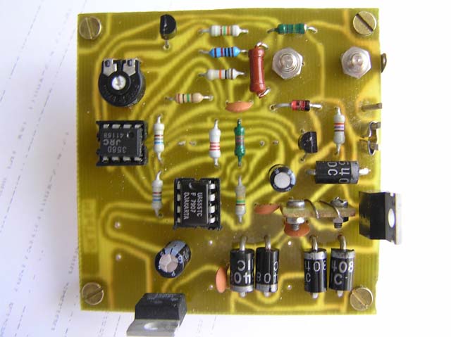
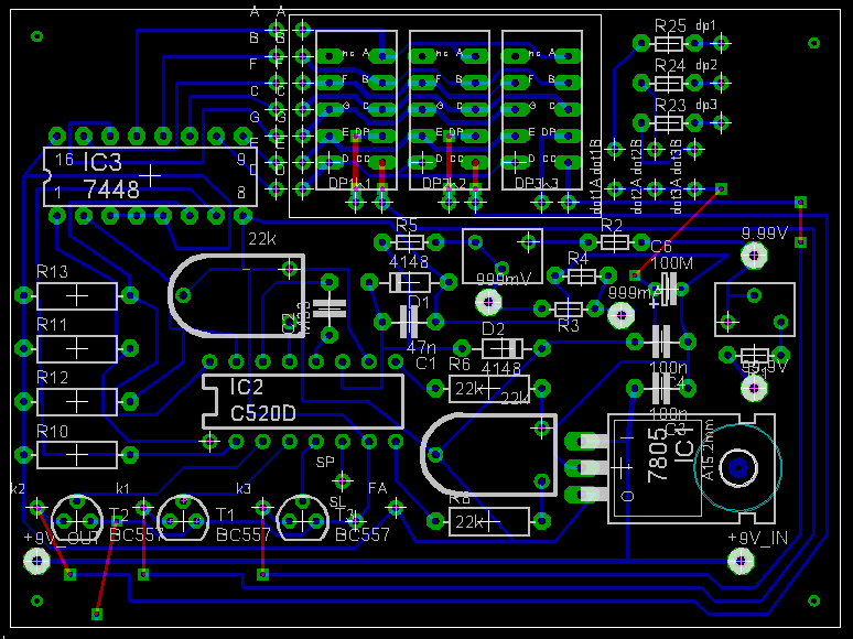
 PCB of charger
To MENU
PCB of charger
To MENU
Development
To MENU

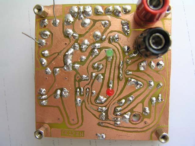
PCB bottom
To MENU

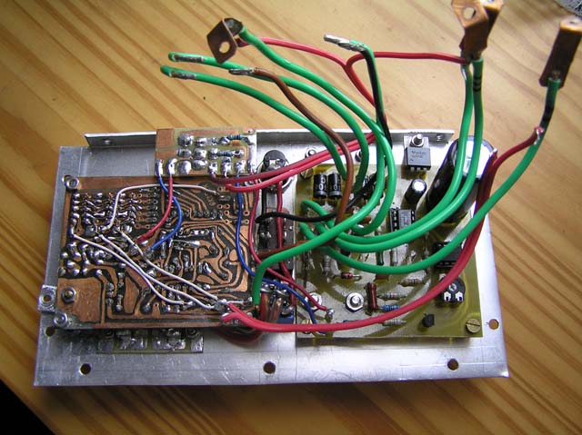
View from top
To MENU
View from bottom
To MENU
Front panel mounting (rear side)
To MENU
Overall view
To MENU
Schema of panel meter
To MENU

PCB of panel meter
To MENU
Best 73 de Libor OK2PEN
To MENU
THE PAGE IS FURTHER DEVELOPED ... --> -->
| | | |