SW RX/QRP loop antenna from a scrapyard
by Karel Julis, OK1UHU, [email protected]
 As a side-effect of my professional work appeared this very cheap and
easy design of a higher-SW loop antenna, which can be made from
materials, found at your local scrapyard. In a fact, I needed some well
performing antenna for 13.5MHz RFID cards experiments. I decided the
single-turn loop.
As a side-effect of my professional work appeared this very cheap and
easy design of a higher-SW loop antenna, which can be made from
materials, found at your local scrapyard. In a fact, I needed some well
performing antenna for 13.5MHz RFID cards experiments. I decided the
single-turn loop.
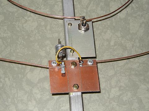
Almost everything you can disclose from the pictures. You need a piece
of an old TV antenna's aluminium boom (about one meter), about 4 meters
of 2mm dia copper wire (from the mains electricity installation wires),
33pF trimmer capacitor (robbed from a wreck of an old tube AM radio), some pieces of PCB
material, some screws&nuts, one BNC female and about half a hour
of time. The detail photos show the top
connection of the wires, the tuning
circuit and a front view of the antenna.
The diameters of the loops are 70cm and 23cm (funny numbers, aren't?). With the trimmer alone,
the antenna tunes very well (with SWR almost 1:1) at 18 and 21 MHz
bands. With 15pF ceramic tube capacitor in paralell to the trimmer, it tunes at 14MHz
(and 13.56MHz ISM, too). The antenna needs a very exact tuning for the
particular operating frequency, even when moved from CW to SSB band
part! Tune the antenna with smallest power usable for your SWR meter,
or you get the fingers burned, hi! That's not a joke - about 5 watt
produce such a voltage!
Thus, PAY ATTENTION! This antenna with the
described construction is suitable for RX or true QRP only! With just a
few watts (5 and above) there is too high voltage at main loop ends (it
means, at the capacitor, too) for the ordinary ceramical tube capacitor
(200V) and the trimmer (about 500V) to withstand! If tried higher, you burn the
capacitor, make sparkfires in a trimmer and carbonize the PCB (HF
thermal effect because of lossy glassfiber)! For such
a disaster, I guess 50 watts PEP(!) and more as pretty sufficient.
But QRP world is beautiful enough, don't you think?
 As a side-effect of my professional work appeared this very cheap and
easy design of a higher-SW loop antenna, which can be made from
materials, found at your local scrapyard. In a fact, I needed some well
performing antenna for 13.5MHz RFID cards experiments. I decided the
single-turn loop.
As a side-effect of my professional work appeared this very cheap and
easy design of a higher-SW loop antenna, which can be made from
materials, found at your local scrapyard. In a fact, I needed some well
performing antenna for 13.5MHz RFID cards experiments. I decided the
single-turn loop.