Homebrew Project Page
This article describes how to build a relatively small loop antenna which can be placed for instance at the balcony. My design is made for modest conditions, e.g. an antenna mounted on a balcony in a block house. It is especially suitable for a two band antenna covering two adjacent amateur radio bands (10/14 MHz, 14/18, etc.).
The antenna was practically tested on 10 MHz band.
The design was inspired by an article by DJ3RW about an unusual design of magnetic loop antenna for 50 MHz band, printed in Funkamateur 10/97.
More information on loop antennas is available in Links section below.
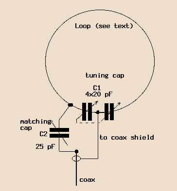
The magloop antenna described here has a different feeding than the usual kind with a coupling loop. Also the tuning capacitor is not mounted at the "top" as usually, it is placed at the "bottom", fed part of the loop.
The loop is tuned by a symmetric, two-section variable capacitor with the common rotor connected to the coax cable shielding.
This antenna is "side-fed" directly from the coax center wire through a (variable) capacitor to one of the two "hot" ends of the tuning capacitor.
A picture will say much more:

You will need a GDO to check resonant frequency of the loop.
Any data in the following list printed in underlined italic indicate measures or values I have tested on my 10/14 MHz loop.

| Bands | Open loop resonant frequency MHz |
|---|---|
| 10/14 | 16-17 |
| 14/18 | 21-22 |
| 18/21 | 24-25 |
| 21/24 | 26-28 |
The resonant frequency of your loop will decrease after you add the tuning capacitor and connect the feed!
If you test the loop now, it should resonate slightly above the desired operating frequency. When I was testing my 10/14 MHz antenna at this point, it resonated between 11 and 16 MHz.
Now there are two possibilities:
You can make it cheaper if you add a dial to the rotor and mark positions for each band.
Well done! :-)
When the antenna is mounted, connect it and test its resonant frequency on your receiver. Loaded antenna will "drop" slightly - mine changed its resonant range from 11-16 MHz to approximately 10-15 MHz over the full variation of the tuning capacitor.
When tuning the antenna, first find the best position of the tuning capacitor by listening. After you have tuned a relatively sharp peak, tune the coupling capacitor (if you have a variable one) for best possible SWR.
My antenna has 1:1 SWR on 10 MHz band without an additional ATU. (In fact the loop itself with all the tuning and coupling circuits is an excellent ATU).
My antenna has SWR 1:1 almost all over 10 MHz band. The SWR is getting slightly worse near band boundaries, but it is just enough to see the meter taking a very moderate move.
I didn't test 14 MHz because of a missing 2nd coupling capacitor. If it worked on 14 MHz the same way, you should be able to cover the whole CW sub-band with SWR 1:1 and most of the band with SWR better than 1:2 if not 1:1.5
I haven't heard much of a DX traffic. But my antenna is on the balcony on the third floor, surrounded by 30 meters high concrete buildings.
I have made QSO's mostly with Europe. Sometimes I get reports which are worse by 3S from stations with comparable output. Sometimes the other OM gives me even 1S more than I can hear him, again if the power is roughly the same.
Some examples (all QSO's were on 10 MHz):
These links might be very useful if you intend to modify the design.
I have received some questions regarding calculation, modification for lower bands, radiation pattern, etc. I am convinced that you can get the best answers from competent people who maintain the above mentioned pages. I actually work in a bank and have no measuring equipment at work or at home :) In fact, the above design was a very lucky experiment.
Please let me know if you try to build this antenna, if you want to make any comments. I am very interested what you think about this article.
In fact, writing this article took me at least three times longer than the time to build the fly-swat. So at least three of you should make some use of it, don't you think so?
73 de Jindra, OK1FOU
| OK1FOU, ex OL4BEV (1981-1984)... QTH:
Praha (Prague), district: API... GRID:
JO70GC... WAZ 15... ITU
ZONE 28... If you feel you that 1) you need more information to be listed in this area, 2) you have to tell me your comments, feel free to send me a mail. Copyright
(C) 1998 Jindra Vavruska |
Thanks to Al, K3TKJ for hosting this page at QSL.NET server. |
Back to OK1FOU main page