Reinstallation due to tightened vibration specifications took place at the AMSAT Spacecraft Integration Laboratory in Orlando, Florida in mid-March 1998.
The trip was sponsored by SRAL, the Finnish Radio Amateur League, RATS, the Radio Amateur Technology Society and the Anritsu Company.
The Solid State Power Amplifier delivers 4 W of RF with - 20 dBc intermodulation distortion with a two tone carrier. The Travelling Wave Tube Amplifier ( courtesy of AMSAT_DL ) delivers 20 W of tone carrier power with the same IMD level. The SSPA can run 7 W in compression and the TWTA delivers 59 W in compression too, so using either for constant amplitude modulations will be very interesting with the 21.4 dBi antenna gain (manufactured to AMSAT-OH design by Distribution Engineering of the Finnish Broadcasting Company) will result in spectacular C/N-ratios !
The antenna horns (164 kb) can be seen here in the final flight configuration with the TWTA and EPC ( Electronic Power Conditioner ).
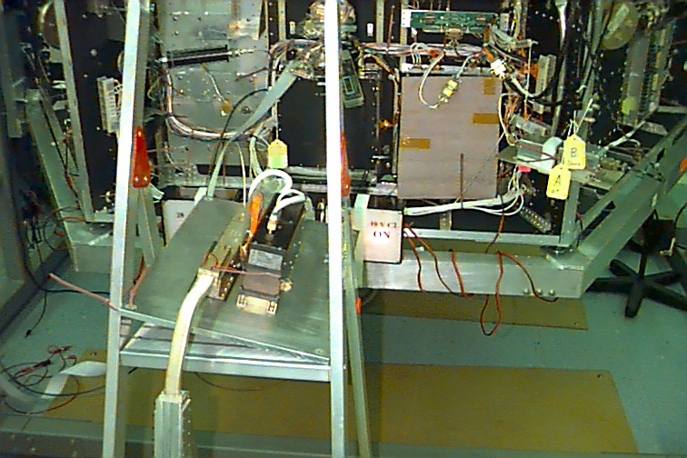
The entire X-band equipment (195 kb) can be seen here. The two black painted modules at the lower right contain the IF processor and upconverter (the topmost piggyback smaller module) and the SSPA, power supply and IHU (Indoor Housekeeping Unit) interface (the lower larger module bolted down onto the ammonia-filled heatpipe system. The two tin cans on "top" of the spacecraft are the antenna horn loads (156 kb) manufactured by KK6TG for this specific purpose. The loads are made from carbon impregnated concrete reinforced with fiber glass. The loads absorb the the high power levels safely and by securing the tin cans down with copper adhesive tape the leakage radiation levels are etremely low.
Before flight installation the hardware was thoroughly retested and the setup seen here (173 kb) was used. The topmost box on the left is the IHU Simulator used for manually setting all necessary control bits, reading telemetry data and generating the spacecraft separation information and a single/dual tone generator at IF with settable level for IF simulation and IMD/linearity measurements. The lower unit in the pile is a power supply for feeding the simulator and the instrument in between is an Anritsu ML2430A power meter kindly loaned by the Anritsu Company. The PC was used for logging the measurement data and the 50 GHz spectrum analyser (kindly loaned by the Boeing Co.) was used for IMD measurements and documentation.
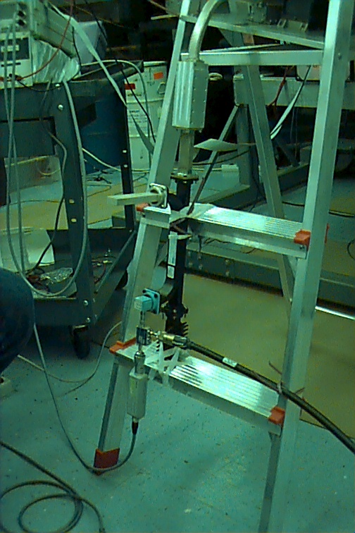
During these tests the power from the SSPA was absorbed in a coaxial load (courtesy of Nokia Telecommunications) and the power sample was tapped with a directional coupler (courtesy of Ylinen Electronics Co.) calibrated first with the power meter. The TWT power was absorbed in a waveguide load (169 kb)and the output was sampled with a 20 dB waveguide coupler calibrated before measurement (also on loan from NTC). The sample was fed via a WG16/SMA adapter to another coaxial coupler used for spectrum analysis sampling. The RF power from the TWT (197 kb) was fed via the flexible/twistable section used in the flight configuration and the block of machined aluminium is the waveguide taper needed to adapt the TWT WG17 to the WG16 used in our measuring components. Note the test scenario with innovative use of the aluminium ladder as a support for the TWTA and EPC !
Our x-band transmitter with redundant HPA has four control bits reserved for setting the AGC level (the AGC is implemented to compensate for combinations of several receiver IF bandwidths and beacons + telemetry carriers over the IF matrix). These four bits essentially control the gain of the transmitter chain and in this manner the operation point can be controlled from no output power to compression with different states of linearity in between. The gain control bits also affect the current consuption of the transmitter and this may be an impetus in some operation conditions for setting the "linearity mode". The current consuption was registered with a DC current clamp (179 kb) (courtesy of FBC) used at different points of DC consuption. In the image you can see the clamp on the 28 V spacecraft bus with the TWTA amp running at 59 W of single carrier average power (worst case). The current meter reading is 4.47 A on the 28 V bus, so you can see that the overall efficiency in this mode is very good.
Here you can see the TWT as flight installed (177 kb) on the spacecraft bay.
Occasionally it was quite busy in the clean room, as you can see (192 kb). From left to right there is Werner Haas (DJ5KQ), Freddy de Guchteneire (ON6UG), Matjaz Vidmar (S53MV), Peter Guelzow (DB2OS) and Konrad Mueller (DG7FDQ) testing the 435 MHz and 2400 MHz transmitters. In the foreground you can see the 35 year old spectrum analyser still up and running and doing a good job of showing the IMD products of our 10 GHz transmitter with a 100 kHz/division dispersion ! On top of the SA is an ICOM 70 cm transceiver used with the SSB Electronic 10 GHz/435 MHz downconverter used to listen to the X-band transmitter. We uplinked on different bands to the downlink and also verified the compatibility with telemetry/beacon/RUDAK carriers simultaneously. We turned the SA around so as to be visible from within the clean room to verify correct operation. Here is an image of Harri (187 kb) fine adjusting the spectrum analyser phase lock. The tests were successful. Something here in Finnish.