Wire trap for 12m WARC band
Wire trap for 12m WARC band
Before we start to assemble our traps, here some general info as introduction :
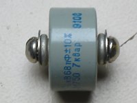 |
To construct a wire trap, you will need a suitable
capacitor. According to some sources, the value in pF should be chosen
around 1.5x the band for which it is intended (so for example, for 20m
band trap = 30 pF, 80m = 120 pF). The best choice is a 'doorknob' type because these are real transmitting capacitors designed for high voltage. You regularly find these on ham flea markets, I purchased a couple on Ebay in Ukraïne. Watch out with Russian doorknob capacitors: there are 2 types : K15U-1 and KVI-3. The first type is best suited for this type of application. The model I had available is 68 pF/6 kV. I checked these capacitors with a magnet : they are completely a-magnetic, including all the screws and washers (this is a must as they will be located inside the coil). Off course you need as well wire. I took 5mm dia aluminum wire (Hint: next time you buy flowers for your XYL, ask your florist, he can get it in rolls of 20m length, they use it for decoration). For the 12 / 17m inverted-V, a trap resonating on the 12m is required, so let us say on 25.2 MHz. |
|
|
|
Now first calculate the value of the inductor (L) to build a LC
circuit with C=68 pF. You can use a handy online calulator, for example
|
|
 |
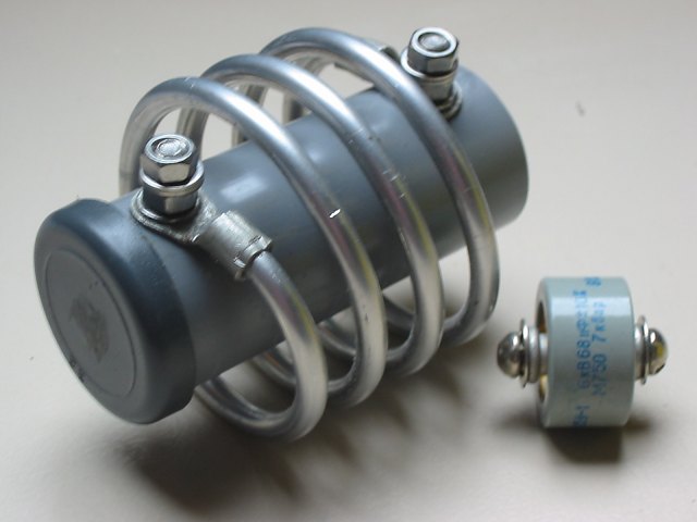
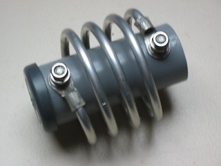
The coil is wound and formed on a suitable pipe (I
used silicone sealant cartridge, dia. is approx 50mm) The ends of
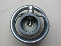
the coil are fitted with eye lugs. Now it is time to mount the capacitor
: mine was fitting nicely inside a 32mm PVC tube (thick walled, 3mm,
resistant to heat version). It must be soldered with 4 eyelugs to both
M5 stainless steel bolts. The calculator shows to be very correct! The exact resonant frequency (use a dip meter) can be fine tuned by stretching or compressing the coil. Finally, glue a cap on the tube side which will be upwards so that no rain can enter the tube. The lower side can remain open. (Inverted-V) During my tests, the antenna works fine with 100w power. Above this level, the capacitor seems to warm up - probably by the high RF current by the very high Q-factor. This causes the capacitance value to drift, the circuit gets out of resonance and the SWR increases quickly > 3. So, this design is not useable for high power.... |