After moving to a new home, I still was in possession of a "DAVIS Weather Monitor II" display console and some sensors, which were originally all interconnected by wire. In the new home, it was impossible to arrange for wiring, and on the other hand, some sensors were no longer 100% reliable ... in particular the hygrometer/temperature unit (Davis part number #07859)

So I took the challenge to :
-
Provide a solution for wireless data transfer of outdoor sensors to indoor receiver
-
Provide new outdoor temperature & relative humidity sensors, next to salvaged wind direction/speed sensor
-
Perform some 'reverse engineering' on actual wired sensors, in order to check if emulation was possible
-
Develop a solution to collect outdoor sensor data and feed to Weather Monitor II console as 'emulated wired sensors'
Solution for Wireless data transfer
As WiFi is available between out- and indoor location, this was the way to go. The DATA itself would be transferred by MQTT protocol, a very easy way to distribute data amongst multiple clients. You have to login as data publisher and subscriber to a MQTT server (a 'broker'), and from then on you can exchange (send and receive) data about a 'topic'. For test purposes, I have chosen the free MQTT broker of HiveMQ (see https://www.hivemq.com/) . The handy thing is that they offer a WebClient console as well, where you can during debugging publish and subscribe data ! Off course, you can provide (for more security) your own MQTT broker, for example running on Raspberri Pi ....
Attention : during project development, I experienced some problems with my ESP 'freezing' ... despite activation of the on-board watchdog and other 'counter-measures'. As these 'stalls' were intermittent, it was impossible to define precisely where the problems was ... the ESP was still running, but were got is stuck ? As a matter of facts, these troubles disappeared when the data transfer rate was lowered. I have the impression that the MQTT library could get jammed when too much data is transferred in a row (buffer overflow ?).
Outdoor sensors
As data transmission was possible by WiFi, choice was made for ESP32 approach with WEMOS LOLIN32 board.
For wind data, I still had the original DAVIS part number # 7911 wind vane & anemometer combination on hand. The schematic diagram is as follows :
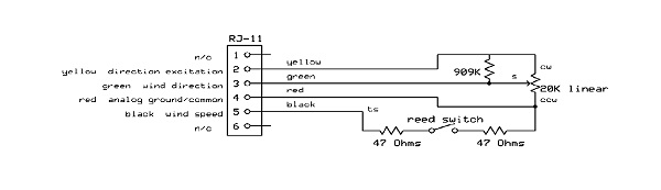
|
Connections |
Function |
|
Black |
Wind speed - Reed contact closure to ground |
|
Green |
Wind direction pot wiper (360° = 20 kOhm) |
|
Yellow |
Supply voltage for pot |
|
Red |
Ground |
Wind direction : The potentiometer is a linear resistance type that is free to rotate 360º with no mechanical stop ( Bourns 6639 20K potentiometer 360º turn no stop, MOUSER stock n° 652-6639S-1-203). I have adjusted it 'NORTH' by the hardware method ... The ESP32 is not 100% accurate/linear with A to D conversion, in particular on the low and high ends, but for this application it works fine (wind direction up to 10° accuracy is more than enough). Direction is read and sent by MQTT every 3,6s,
Wind speed : There is one pulse (contact closure) per revolution. If you count the number of pulses in 3600ms, you have a direct reading in km/h. I have chosen to sample every 3,6s to be able to read the slightest wind with best accuracy. At wind speed of 150 hm/h, contact closure time is in the order of only 3 ms ... but I have taken 15 ms as minimum interval between 2 contact closures to eliminate false readings by 'reed contact bounce' - this will still make possible to read winds up to 150 km/h or so... The reed contact status is feeding an interrupt on board of the ESP. Data is send by MQTT every 3,6s, together with wind direction information.
Temperature, humidity, barometric pressure : are measured by a BOSCH BME-280 sensor, readout by I2C every 36 seconds and then sent by MQTT .
Sketch for WEMOS LOLIN32 outdoor sensor unit :
/*
**************************************************************************
***********                  OUTDOOR WEATHER SENSOR              *********
***********           FOR ESP32 type  WEMOS   LOLIN 32   !!!!!!  *********
***********                   by ON7EQ 05_2021                   *********
**************************************************************************


//////////////////////   inspired from   ////////////////
// BMx280_I2C.ino
//
// shows how to use the BMP280 / BMx280 library with the sensor connected using I2C.
//
// Copyright (c) 2018 Gregor Christandl
//
// connect the AS3935 to the Arduino like this:
//
// Arduino - BMP280 / BME280
// 3.3V ---- VCC
// GND ----- GND
// SDA ----- SDA
// SCL ----- SCL
// some BMP280/BME280 modules break out the CSB and SDO pins as well:
// 5.3V ---- CSB (enables the I2C interface)
// GND ----- SDO (I2C Address 0x76)   see #define I2C_ADDRESS
// 3.3V ---- SDO (I2C Address 0x77)   see #define I2C_ADDRESS
// other pins can be left unconnected.
///////////////////////////////////////////////////////


===================================================================
DAVIS Vantage Pro & Vantage Pro 2    Wind Sensor (speed & direction
===================================================================

On RJ-45 plug terminals:

Black =  pulse from anemometer. Connect to Digital 2 pin, and use a 4k7 resistor as pull up to + 5v.
         use a 10 to 22nF capacitor from pin D2 to ground to debounce the reed switch of anemometer

Red =    Ground

Green =  Wiper  of Wind direction vane - connect to analog input.  Use a 1 ... 10 µF / 16v capacitor between input and ground (observe C polarity) to avoid jitter

Yellow = + 3,3 or 5v (reference of potentiometer)

*/

// include EEPROM write - required if you want to memorize azimuth offset
#include <EEPROM.h>

#include <esp_task_wdt.h>       // Watchdog
#define WDT_TIMEOUT 30          // 30 seconds no connection with broker will force a reset

#include <Arduino.h>

#include <Wire.h>             // I2C

#include <BMx280I2C.h>        // Bosch BMx280  sensor
#define I2C_ADDRESS 0x76
//create a BMx280I2C object using the I2C interface with I2C Address 0x76
BMx280I2C bmx280(I2C_ADDRESS);

#include <WiFi.h>

const char* ssid     = "MyWiFI_SSID";	// change as required
const char* password = "MyPassword";		// change as required

IPAddress local_IP(???, ???, ???, ???);		// Fixed ip chosen, replace ??? by your ip
IPAddress gateway(???, ???, ???, ???);
IPAddress subnet(255, 255, 255, 0);
IPAddress primaryDNS(195, 130, 130, 4);       //Telenet  isp
IPAddress secondaryDNS(8, 8, 8, 8);           //Google

#include <SPI.h>

#include <PubSubClient.h>

const char* server = "broker.hivemq.com";

WiFiClient MyWiFiClient;
PubSubClient mqttClient(MyWiFiClient);


////////////   DEFINE VARIABLES   //////////

uint32_t PublishIntervalWind = 3600;                 // Publish interval for wind in ms
uint32_t LastPublishTimeWind ;                       // last publish interval for wind

uint32_t PublishIntervalTemp = 36000;                // Publish interval for Temp/Humid/Baro in ms
uint32_t LastPublishTimeTemp;                        // last publish interval for Temp/Humid/Baro

uint32_t LastBrokerNoConnectTime ;                       // last publish interval for wind

int check_connection = 0;                              // counter increments at each publication on MQTT server

uint32_t Wind_rpm_meas_interval = 3600;            // fixed for DAVIS wind vane !
uint32_t Wind_rpm_meas_start;                      // start of wind rpm measure
byte wind_measuring = 0;                                // during measure = 1
volatile uint32_t RPMTops;                         // RPM tops counter in interrupt routine
volatile uint32_t ContactTime;                     // Timer to avoid contact bounce in interrupt routine

float RPM;            // RPM count

int Direction ;       // Wind direction

int PotValue = 0;      // variable to store the value coming from the potentiometer
int DirCorr = 0;       // Correction on direction ( - 360  to + 360)

float Temperature ;
float Pressure;
float Humidity;


//#define CalPin (A1)    // define the input pin to initiate direction calibration @ startup. Ground pin to calibrate
//byte DirCorrB1 = 0;    // 2 bytes of DirCorr
//byte DirCorrB2 = 0;


//////////   Define I/O pins //////////////

#define RPMsensor (15)      //The GPIO pin location of the anemometer sensor = GPIO15
#define PotPin (36)         // define the input pin for the wind vane potentiometer
#define LEDpin (02)         // define the output pin for the LED blinker


/////// Callback routine /////////
      void callback(char* topic, byte* payload, unsigned int length) {
        Serial.print("Message arrived [");
        Serial.print(topic);
        Serial.print("] ");
        for (int i = 0; i < length; i++) {
          Serial.print((char)payload[i]);
        }
        Serial.println();
      }


/////   Reconnect subroutine //////////
        void reconnect() {
          // Loop until we're reconnected
      while (!mqttClient.connected()  and (WiFi.status() == WL_CONNECTED) ) {
            Serial.print("Attempting MQTT connection with broker '");
            Serial.print(server);
            Serial.println("' ...");
            Serial.println();
            // Attempt to connect
            if (mqttClient.connect("clientId-choose_an_ID")) {
              Serial.println("Broker connected !");
              Serial.println();
            // 5 LED flashes to confirm broker connected
              delay(1000);

              for (int i=0;i<10;i++) {
              digitalWrite(LEDpin, !digitalRead(LEDpin));
              delay(200);
                  }


              // Once connected, publish an announcement...
              mqttClient.publish("my_weather_station/RSSI", "STARTED");


            } else {
              Serial.print("FAILED, rc=");
              Serial.print(mqttClient.state());
              Serial.println(" try again in 5 seconds");
              Serial.println();
              Serial.println();

              // Wait 5 seconds before retrying
              delay(5000);
            }
          }
        }

/////// This is the function that interrupt calls to measure  RPM /////

// (With an ESP32 board, all the GPIO pins can be configured to function as interrupt request inputs)

 void IRAM_ATTR rpm ()   {

    if ((millis() - ContactTime) > 15 ) {  // debounce of REED contact. With 15ms speed more than 150 km/h can be measured
      RPMTops++;
      ContactTime = millis();
    }

}
//// end of RPM measure


//////////////////////////////////   S E T U P   ///////////////////////////////////////////////////

void setup()    {

////   Config I/O pins  ////
  pinMode(RPMsensor, INPUT_PULLUP);
  attachInterrupt(RPMsensor, rpm, FALLING);

  pinMode(LEDpin, OUTPUT);
  digitalWrite(LEDpin, HIGH);

  Serial.begin(115200);                               // DEBUG serial
  delay(10);

  mqttClient.setServer(server , 1883);
  mqttClient.setCallback(callback);


////////// CONFIG & ENABLE WiFi ////////

   WiFi.disconnect();

   delay (500);

  if (!WiFi.config(local_IP, gateway, subnet, primaryDNS, secondaryDNS)) {
    Serial.println("STA Failed to configure");
      }

  Serial.println("");
  Serial.println("");
  Serial.print("Connecting to ");
  Serial.println(ssid);

  WiFi.begin(ssid, password);

  esp_err_t esp_wifi_set_max_tx_power(78);    // set max power on WiFi

  while (WiFi.status() != WL_CONNECTED) {

  // 10 LED flashes to signal WiFi not connected

    for (int i=0;i<20;i++) {
    digitalWrite(LEDpin, !digitalRead(LEDpin));
    delay(50);
        }

    Serial.print(".");
      }

  Serial.println("");
  Serial.println("----- WiFi connected! -----");
  Serial.print("RSSI: ");
  Serial.print(WiFi.RSSI());
  Serial.println("dBm");
  Serial.print("IP address: ");
  Serial.println(WiFi.localIP());
  Serial.print("ESP Mac Address: ");
  Serial.println(WiFi.macAddress());
  Serial.print("Subnet Mask: ");
  Serial.println(WiFi.subnetMask());
  Serial.print("Gateway IP: ");
  Serial.println(WiFi.gatewayIP());
  Serial.print("DNS: ");
  Serial.println(WiFi.dnsIP());
  Serial.println("--------------------------");


  WiFi.setAutoReconnect(true);
  WiFi.persistent(true);

  delay(1000);

  Wire.begin();

  //begin() checks the Interface, reads the sensor ID (to differentiate between BMP280 and BME280)
  //and reads compensation parameters.
  if (!bmx280.begin())  {
    Serial.println("begin() failed. check your BMx280 Interface and I2C Address.");
    while (1);
     }

  if (bmx280.isBME280())   Serial.println("sensor is a BME280");
  else   Serial.println("sensor is a BMP280");
  Serial.println("--------------------------");


  //reset sensor to default parameters.
  bmx280.resetToDefaults();

  //by default sensing is disabled and must be enabled by setting a non-zero
  //oversampling setting.
  //set an oversampling setting for pressure and temperature measurements.
  bmx280.writeOversamplingPressure(BMx280MI::OSRS_P_x16);
  bmx280.writeOversamplingTemperature(BMx280MI::OSRS_T_x16);

  //if sensor is a BME280, set an oversampling setting for humidity measurements.
  if (bmx280.isBME280())  bmx280.writeOversamplingHumidity(BMx280MI::OSRS_H_x16);

  // Ensure publication at startup
  LastPublishTimeTemp = millis() - PublishIntervalTemp - 5000;
  LastPublishTimeWind = millis() - PublishIntervalWind - 5000;

}

//////////////////////////////     L O O P    //////////////////////////////////////////////////

void loop()   {

  /// Check if WiFi still connected, else reboot ESP
    if (WiFi.status() != WL_CONNECTED)  ESP.restart();


  // Check if broker connected
  if (!mqttClient.connected()) {
    delay(2000);                        // Not connected ...
    digitalWrite(LEDpin, LOW);
    delay(1500);
    digitalWrite(LEDpin, HIGH);
    delay(1500);
    reconnect();
  }

  esp_task_wdt_reset();                   // we have broker connected, reset watchdog !

  mqttClient.loop();

/*  // publish new data
  temperature = temperature + 1;
   Serial.print("temperature=");
   Serial.print(temperature);
   Serial.println();
*/


 //////////////////  measure data   /////////////////////


 //// Measure Wind RPM ///


           RPMTops = 0;
           sei();                           //Enables interrupts
           delay (Wind_rpm_meas_interval);  //Wait measurement interval, we can use delay() as no other process needs to run ...
           cli();                           //Disable interrupts

            RPM = RPMTops;                 // no multiplication if sample time 3600s

              Serial.print("Wind Speed=");
              Serial.println(int(RPM), DEC);

 //// Measure Wind Direction ///

          PotValue = analogRead(PotPin);
          Direction = map(PotValue, 0, 4095, 0, 359);

          Serial.print("Wind Direction=");
          Serial.println(int(Direction), DEC);

 //// Measure BMX280 ///

if (!bmx280.measure())
  {
    Serial.println("could not start measurement, is a measurement already running?");
    return;
  }

  //wait for the measurement to finish
  do
  {
    delay(100);
  } while (!bmx280.hasValue());

    Serial.print("Pressure: ");
    Pressure = bmx280.getPressure() / 100 ;
    Serial.println(Pressure);
    Pressure = Pressure * 10 ;                    // prepare for MQTT transfer, up to 1 tenth precision

    Serial.print("Temperature: ");
    Temperature = bmx280.getTemperature();
    Serial.println(Temperature);
    Temperature = Temperature * 10 ;              // prepare for MQTT transfer, up to 1 tenth precision

  if (bmx280.isBME280())    {
    Serial.print("Humidity: ");
    Humidity = bmx280.getHumidity();
    Serial.println(Humidity);
    Humidity = Humidity * 1 ;                     // prepare for MQTT transfer, no decimal precision required
      }

  //important: measurement data is read from the sensor in function hasValue() only.
  //make sure to call get*() functions only after hasValue() has returned true.


    Serial.println("------------------------------");

 //  }      /// end measuring cycle


/////////////////// Publish data  /////////////////////

if ((millis() - LastPublishTimeWind) > PublishIntervalWind) {

  digitalWrite(LEDpin, LOW);
  mqttClient.publish("my_weather_station/wind_direction", String(int(Direction), DEC).c_str());
  delay(100);   // delays are required to avoid buffer overflow @ receive side ...
  mqttClient.publish("my_weather_station/wind_speed", String(int(RPM), DEC).c_str());
  digitalWrite(LEDpin, HIGH);
  LastPublishTimeWind = millis();
  };

if ((millis() - LastPublishTimeTemp) > PublishIntervalTemp) {

  digitalWrite(LEDpin, LOW);
  delay(100);   // delays are required to avoid buffer overflow @ receive side ...
  mqttClient.publish("my_weather_station/temperature", String(int(Temperature), DEC).c_str());
  delay(100);
  mqttClient.publish("my_weather_station/pressure", String(int(Pressure), DEC).c_str());
  delay(100);
  mqttClient.publish("my_weather_station/humidity", String(int(Humidity), DEC).c_str());
  delay(100);
  mqttClient.publish("my_weather_station/RSSI", String(WiFi.RSSI()).c_str());
  delay(100);
  check_connection = check_connection + 1 ;             // check connection counter
  mqttClient.publish("my_weather_station/check_connection", String(int(check_connection),DEC).c_str());
  delay(100);
  LastPublishTimeTemp = millis();
  digitalWrite(LEDpin, HIGH);
   };


////  END LOOP
}
Emulation of sensors for Weather Monitor II console
For emulation of sensors, choice was made as well for an ESP32 solution, now with WEMOS LOLIN LITE board (the'NON-LITE' version should work as well).
Wind direction :
0 to +2,5 V is read by DAVIS WM2 as 0° to 360°, in a linear way - easy ! Generated by a D to A port on the ESP with aid of LEDC function, on basis of direction information received by MQTT.
Wind speed :
Every 3,6 s data is received by MQTT, and transformed into pulses fed to DAVIS WM2. Between the ESP32 and DAVIS WM2 I inserted a NPN transistor, connected with its 'open collector' to the WM2 - this simulates the reed contact closure.
Temperature and Relative Humidity, emulation of DAVIS Part n° #07850:
Temperature is fed as a positive voltage on the yellow wire, in opposition to ground (red and black wires). The voltage get lower as temperature increases , but not in a 100% linear way. At 20°C, the voltage will be 0,975 Volt, at -20°C 2,09 Volt, at +50°C 0,386 Volt as I measured.

The relation between temperature and voltage/reading on WM2 can be determined by a test setup, where a potentiometer is defining the temperature, the data put into EXCEL, which will generate a formula.
Voltage = 0,000004 t³ - 0,00007 t² - 0,0295 t + 1,5693
This third order formula seems adequate between -15°C and + 35°C about, where deviation is in the order of 0,1 to 0,2 °C. A fourth order formula would maybe give even more accurate results (sse above graph), but deviation less than 0,5° is quite OK !
Voltage is generated by a D to A port on the ESP with aid of LEDC function, on basis of direction information received by MQTT.
Emulation of relative humidity is another story !
In the original sensor, a device is used which changes capacitance in function of humidity. This device is inserted in a high frequency oscillator with a 555 IC, working at about 70 kHz, this signal is divided by 8 by another IC, and then fed to the WM2 console on the GREEN wire as square wave signal, with amplitude of about 2,5V and duty cycle of 50%. Following frequencies provide corresponding RH indication, in a linear manner:
| Frequency (Hz) | RH indication |
| 9750 | 1% |
| 8530 | 50% |
| 7280 | 100% |
Note that for RH indication below 20% with the original DAVIS sensor, accuracy can be up to 10% off... with BME-280, far better results are expected.
Now comes the tricky thing : about every second or so, the WM2 produces a pulsed 'CONTROL SIGNAL' on the BLUE wire, amplitude 2,5 Volt, which has the effect of providing a 'CALIBRATION SIGNAL' of 6425 Hz / duty cycle 50% (instead of above frequency) on the GREEN wire.
So, the BLUE wire must be monitored by the ESP and provide this calibration signal instead of RH when requested.
For frequency generation with the ESP32, LEDC function is as well used to generate a PWM signal with 50% duty cycle (1 byte resolution).
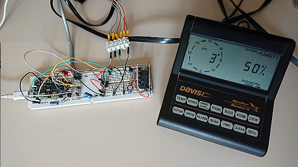
Setup for testing...
Feeding signals from ESP32 to WM2
Signals are fed to WM2 console by using the DAVIS 'junction box', providing a single 8 wires cable between junction box and console, and inputs for temp/RH sensor, wind sensor and rainfall sensor (not used here).
Hereby the corresponding wire colors between all cables !
| 8 wire between WM2 and junction box | Input on junction box | Function |
| Grey | Blue Humidity | Control pulses |
| Orange | Green anemometer | Wind direction pot wiper |
| Black | White Humidity | +2,5v supply to sensor, not used here |
| Red | Black anemometer | Wind speed - Reed contact |
| Green | Rain sensor (not used here) | Reed switch contact |
| Yellow | Red Humidity | Ground (temperature & RH) |
| Blue | Yellow Humidity | Temperature |
| Brown | Green humidity | RH & calibration frequency |
Sketch for WEMOS LOLIN32 LITE outdoor unit :
/*
**************************************************************************
***********                  DAVIS SENSOR EMULATION              *********
***********           FOR ESP32 type  WEMOS   LOLIN Lite         *********
***********                   by ON7EQ 05/2021                   *********
**************************************************************************


*/

// include EEPROM write - required to memorize azimuth offset
// #include <EEPROM.h>

#include <Arduino.h>

//#include <Wire.h>             // I2C

#include <esp_task_wdt.h>       // Watchdog
#define WDT_TIMEOUT 300          // 300 seconds no data coming in forces reset


#include <WiFi.h>

const char* ssid     = "MyWiFI_SSID";	// change as required
const char* password = "MyPassword";		// change as required

IPAddress local_IP(???, ???, ???, ???);	// Fixed ip chosen, replace ??? by your ip
IPAddress gateway(???, ???, ???, ???);
IPAddress subnet(255, 255, 255, 0);
IPAddress primaryDNS(195, 130, 130, 4);       //Telenet  isp
IPAddress secondaryDNS(8, 8, 8, 8);           //Google
#include <SPI.h>

#include <PubSubClient.h>


WiFiClient MyWiFiClient;
PubSubClient mqttClient(MyWiFiClient);


////////////   DEFINE VARIABLES   //////////

const char* server = "broker.hivemq.com";

String wind_dir = "--";                 // Wind direction as character string
  int wind_dir_int = 0;                   // Wind direction string converted to integer

  String wind_spd = "---";                // Wind speed as character string
  int wind_spd_int = 0;                   // Wind speed string converted to  integer
  int wind_spd_max = 0;                   // Max wind speed

  String temperature = "---";             // temperature as character string (with 10x factor)
  int temperature_int = 999 ;             // temperature as integer
  int last_temperature_int = 999;         // last valid temp
  float temp_to_volt;                     // voltage to produce on output pin

  String pressure = "-----";              // pressure as character string  (with 10x factor)
  int pressure_int = 0 ;                  // pressure as integer
  int last_pressure_int = 0    ;          // last valid pressure

  String humidity = "---";                // humidity as character string  (with 1x factor)
  int humidity_int = 0 ;                  // humidity as integer
  int humidity_freq = 5000;               // frequency to generate for humidity
  int last_humidity_int = -99;            // last valid humidity
  byte cal_freq = 0;                      // 1 when RH cal frequency generated

  long int wind_spd_int_start ;           // period between 2 pulses (not including the pulse !)

  long int msg_rx_time;                   // timestamp msg received from MQTT broker


//////////   Define I/O pins //////////////

// We use LEDC PWM to generate DA outputs
// use first channel of 16 channels (started from zero)
#define LEDC_CHANNEL_0     0                    //  Wind direction

// use second channel of 16 channels (started from zero)
#define LEDC_CHANNEL_1     1                    //  Outside temperature

// use 13 bit precision for LEDC timer
#define LEDC_TIMER_13_BIT  13     // 13 bit resolution = 8192 enough for outside temp & wind direction

// use nineth channel of 16 channels (started from zero)
#define LEDC_CHANNEL_8     8                    //  Outside humidity

// use 13 bit precision for LEDC timer
#define LEDC_TIMER_1_BIT  1     //     1 bit resolution  as PWM fixed 50%


// use 1000 Hz as a LEDC base frequency
#define LEDC_BASE_FREQ     1000

// Wind vane voltage output pin
#define WIND_DIR_PIN    5

// Anemometer output pin
#define WIND_SPD_PIN    22

// Outside temp output pin
#define TEMPERATURE_PIN    13

// RH 'control' pin input
#define RH_CTRL_PIN    33

// RH frequency output pin
#define RH_FREQ_PIN    17

// define the output pin for the LED blinker
#define LEDpin 32

// Arduino like analogWrite
// Value has to be between 0 and valueMax

void ledcAnalogWrite(uint8_t channel, uint32_t value, uint32_t valueMax = 360) {        /// 360 degrees is max
  // calculate duty, 8191 from 2 ^ 13 - 1
  uint32_t duty =  6350  * min(value, valueMax) ;    /// 6300 = 8191 * 2,50 / 3,30
  duty = duty / valueMax;
  // write duty to LEDC
  ledcWrite(channel, duty);
   }

void ledcAnalogWrite2(uint8_t channel, uint32_t value, uint32_t valueMax = 3400) {      ///  volt x 1000 for handling as integer
  // calculate duty, 8191 from 2 ^ 13 - 1
  uint32_t duty = (8191 * min(value, valueMax)) ;
  duty = duty / valueMax;
  // write duty to LEDC
  ledcWrite(channel, duty);
  //  ledcWrite(channel, 8191);             // Debug

   }


/////// Callback routine /////////
      void callback(char* topic, byte* payload, int length) {

      esp_task_wdt_reset();                   // we have data coming in, reset watchdog !

    /// Debug only
    /*
         Serial.print("Message arrived [");
            Serial.print(topic);
            Serial.print("] ");
            for (int i = 0; i < length; i++) {
              Serial.print((char)payload[i]);
            }
            Serial.println();
    */

/// Blink LED
    digitalWrite(LEDpin, LOW);
    msg_rx_time = millis ();

      if(strcmp((topic),"my_weather_station/wind_direction") == 0){


             /// Convert string to integer

                  wind_dir = "";

                  if (length < 4) {

                        for (int j=0;j<length;j++) {
                        wind_dir = wind_dir + (char)payload[j];
                            }
                     }


                  wind_dir_int = wind_dir.toInt();

                  Serial.print("Wind direction = ");
                  if (length == 1) Serial.print("00");
                  if (length == 2)  Serial.print("0");
                  Serial.print(wind_dir_int);
                  Serial.println("°");
                 }

       if(strcmp((topic),"my_weather_station/wind_speed") == 0){


                  wind_spd = "";

                  if (length < 4) {

                        for (int j=0;j<length;j++) {
                        wind_spd = wind_spd + (char)payload[j];
                          }
                  }

                  wind_spd_int = wind_spd.toInt();

                  Serial.print("Wind speed = ");
                  Serial.print (wind_spd_int);
                  Serial.println(" km/h");
                  Serial.println("--------------------------");  /// Data separator
                 }

       if(strcmp((topic),"my_weather_station/temperature") == 0){

         ///     if(strcmp((topic),"testdata") == 0){            // DEBUG

         /// Convert string to integer

              temperature = "";

              if (length < 5) {

                            for (int j=0;j<length;j++) {
                            temperature = temperature + (char)payload[j];
                                  }
                    }

              temperature_int = temperature.toInt();

              // check if consistant !

              if (last_temperature_int == 999)  last_temperature_int = temperature_int ;    // first check always 'valid'

              if ( abs (temperature_int - last_temperature_int) > 50) {
                temperature_int = last_temperature_int;                   // consider 'last valid' if delta > 5°
                 }

              else {
                last_temperature_int = temperature_int ;                  // update last good temp
                     }

              Serial.print("Temperature = ");
              Serial.print (temperature_int);
              Serial.println("°C (x10)");
              Serial.print("Temp Voltage = ");
              Serial.println(temp_to_volt);
              Serial.println("");

             }

        if(strcmp((topic),"my_weather_station/humidity") == 0){


             /// Convert string to integer

                  humidity = "";

                   if (length < 4) {

                            for (int j=0;j<length;j++) {
                            humidity = humidity + (char)payload[j];
                                  }
                        }

                  humidity_int = humidity.toInt();

                  if (last_humidity_int == -99)  last_humidity_int = humidity_int ;    // first check always 'valid'

                  if (abs (humidity_int - last_humidity_int) > 20) {
                    humidity_int = last_humidity_int;                   // consider 'last valid' if delta > 20%
                       }

                  else {
                    last_humidity_int = humidity_int ;
                       }

                 Serial.print("Rel.Humidity = ");
                 Serial.print (humidity_int);
                 Serial.println(" %");
                 Serial.print("Rel.Humidity freq = ");
                 Serial.print (humidity_freq);
                 Serial.println(" Hz");
                 Serial.println("");

                 // Add some status info ...

                 Serial.print("RSSI: ");
                 Serial.print(WiFi.RSSI());
                 Serial.println("dBm");
                 Serial.println("--------------------------");

                 }


      } /// End callback routine


/////   Reconnect subroutine //////////
        void mqtt_reconnect() {

          mqttClient.disconnect();

          // Loop until we're reconnected
          while (!mqttClient.connected()  and (WiFi.status() == WL_CONNECTED) ) {
            Serial.print("Attempting MQTT connection with broker '");
            Serial.print(server);
            Serial.println("' ...");
            Serial.println();

            // Attempt to connect
            if (mqttClient.connect("clientId-choose_an_ID_as_you_wish")) {
              Serial.println("Broker connected !");
              Serial.println();

               // 5 LED flashes to confirm broker connected
              delay(1000);

              for (int i=0;i<10;i++) {
              digitalWrite(LEDpin, !digitalRead(LEDpin));
              delay(200);
                  }


              // Once connected, publish an announcement...
              //mqttClient.publish("my_weather_station/RSSI", "STARTED");

              // ... and resubscribe
              mqttClient.subscribe("my_weather_station/#");


            } else {
              Serial.print("FAILED, rc=");
              Serial.print(mqttClient.state());
              Serial.println(" try again in 5 seconds");
              Serial.println();
              Serial.println();

              // Wait 5 seconds before retrying
              delay(5000);
            }
          }
        }


////////// CONFIG & ENABLE WiFi ////////

void WiFi_connect()           {

          WiFi.disconnect();

          if (!WiFi.config(local_IP, gateway, subnet, primaryDNS, secondaryDNS)) {
            Serial.println("STA Failed to configure");
              }

          Serial.println("");
          Serial.println("");
          Serial.print("Connecting to ");
          Serial.println(ssid);

          WiFi.begin(ssid, password);

          // esp_err_t esp_wifi_set_max_tx_power(78);    // set max power on WiFi

          while (WiFi.status() != WL_CONNECTED) {
              Serial.print(".");

          // 20 LED flashes to signal WiFi connecting

            for (int i=0;i<40;i++) {
              digitalWrite(LEDpin, !digitalRead(LEDpin));
              delay(20);
                }

              }

          Serial.println("");
          Serial.println("----- WiFi connected! -----");
          Serial.print("RSSI: ");
          Serial.print(WiFi.RSSI());
          Serial.println("dBm");
          Serial.print("IP address: ");
          Serial.println(WiFi.localIP());
          Serial.print("ESP Mac Address: ");
          Serial.println(WiFi.macAddress());
          Serial.print("Subnet Mask: ");
          Serial.println(WiFi.subnetMask());
          Serial.print("Gateway IP: ");
          Serial.println(WiFi.gatewayIP());
          Serial.print("DNS: ");
          Serial.println(WiFi.dnsIP());
          Serial.println("--------------------------");

          WiFi.setAutoReconnect(true);
          WiFi.persistent(true);

          delay(1000);
    }  // end void WiFiconnect


//////////////////////////////////   S E T U P   ///////////////////////////////////////////////////

void setup()    {

/////    Config Watchdog
  esp_task_wdt_init(WDT_TIMEOUT, true);         //enable panic so ESP32 restarts
  esp_task_wdt_add(NULL);                       //add current thread to WDT watch


////   Config I/O pins  ////

  // Setup timer and attach timer to a led pin - used for PWM

  ledcSetup(LEDC_CHANNEL_0, LEDC_BASE_FREQ, LEDC_TIMER_13_BIT);

  ledcAttachPin(WIND_DIR_PIN, LEDC_CHANNEL_0);
  ledcAttachPin(TEMPERATURE_PIN, LEDC_CHANNEL_1);

  ledcSetup(LEDC_CHANNEL_8, 30000, LEDC_TIMER_1_BIT);
  ledcAttachPin(RH_FREQ_PIN, 8);

  digitalWrite(WIND_SPD_PIN, HIGH);       // HIGH = 0 volt = logic high on wind pulse input
  pinMode(WIND_SPD_PIN, OUTPUT);

  pinMode(RH_CTRL_PIN, INPUT);            // Control pin RH CAL frequency
  pinMode(RH_FREQ_PIN, OUTPUT);           // RH Frequency generator output

  digitalWrite(LEDpin, HIGH);
  pinMode(LEDpin, OUTPUT);

  Serial.begin(115200);                               // DEBUG serial
  delay(100);

  Serial.println("Starting ESP ....");
  delay(100);

  mqttClient.setServer(server , 1883);
  mqttClient.setCallback(callback);

  WiFi_connect();

  esp_task_wdt_reset();                   // reset watchdog before entering loop

} // end of SETUP

//////////////////////////////     L O O P    //////////////////////////////////////////////////

void loop()   {

  // Serial.println("Looping the loop");

  /// Check if WiFi still connected, else reboot ESP
  // if (WiFi.status() != WL_CONNECTED)  ESP.restart();


  if (WiFi.status() != WL_CONNECTED) {

    Serial.println("--------------------------");
    Serial.println("WiFi disconnected !!!");
    Serial.println("Attempting 'soft'reconnect...");
    WiFi.reconnect();
    delay (5000);
        if (WiFi.status() != WL_CONNECTED) {
             WiFi.disconnect();
             Serial.println("Attempting 'hard' reconnect...");
             delay (1000);
             WiFi_connect();
            }
    Serial.println("--------------------------");
    }


  /// Check if broker connected
  if (!mqttClient.connected()) {
    delay(2000);                        // Not connected ...
    digitalWrite(LEDpin, LOW);
    delay(1500);
    digitalWrite(LEDpin, HIGH);
    delay(1500);
    mqtt_reconnect();
  }

  mqttClient.loop();


//////////// Output voltage on Wind Direction pin

// ledcAnalogWrite(LEDC_CHANNEL_0, 10);           // debug
 ledcAnalogWrite(LEDC_CHANNEL_0, wind_dir_int);


//////////// Output pulse on Wind Speed pin

if (wind_spd_int > 0) {           // only if there is wind????

      // wind_spd_int = 100;          // DEBUG

      digitalWrite(WIND_SPD_PIN, HIGH);
      if (millis() - wind_spd_int_start + 20 > 3600 / wind_spd_int) {             // + 5 ms per loop is about 3600
            digitalWrite(WIND_SPD_PIN, LOW);
            delay (20);                                                           // 'Reed' pulse 20ms
            digitalWrite(WIND_SPD_PIN, HIGH);
            wind_spd_int_start = millis() ;
            }
         }

//////////// Output voltage on Temperature pin

//   ledcAnalogWrite2(LEDC_CHANNEL_1, 1650);           // debug

temp_to_volt = 1.5728 + (0.000000005 * temperature_int * temperature_int * temperature_int) - (0.0000009 * temperature_int * temperature_int) - (0.003 * temperature_int) ;  // up to 40°

temp_to_volt = temp_to_volt + 0.020 - (0.000085 * temperature_int);                // correction for RC network

temp_to_volt = temp_to_volt * 1000;

ledcAnalogWrite2(LEDC_CHANNEL_1, int(temp_to_volt));


//////////// Relative Humidity output


 //

 if (digitalRead (RH_CTRL_PIN)  == HIGH )  {                // CAL pulse on control line
       // Serial.println("CAL pulse on CTRL line");
       //digitalWrite(RH_FREQ_PIN, HIGH);
       //tone (6425);
      if (cal_freq == 0) {
                ledcWriteTone(8, 6425);
                cal_freq = 1;
            }
    }

    else {
       //  Serial.println("no CAL pulse on CTRL line");      // no CAL pulse on control line
       // digitalWrite(RH_FREQ_PIN, LOW);
       if (cal_freq == 1) {
                humidity_freq = map (humidity_int , 1 , 100 , 9750 , 7280) ;
                ledcWriteTone(8, humidity_freq);
                cal_freq = 0;
            }
     }

 //


    if (millis() - msg_rx_time > 200) digitalWrite(LEDpin, HIGH);

////  END LOOP
}
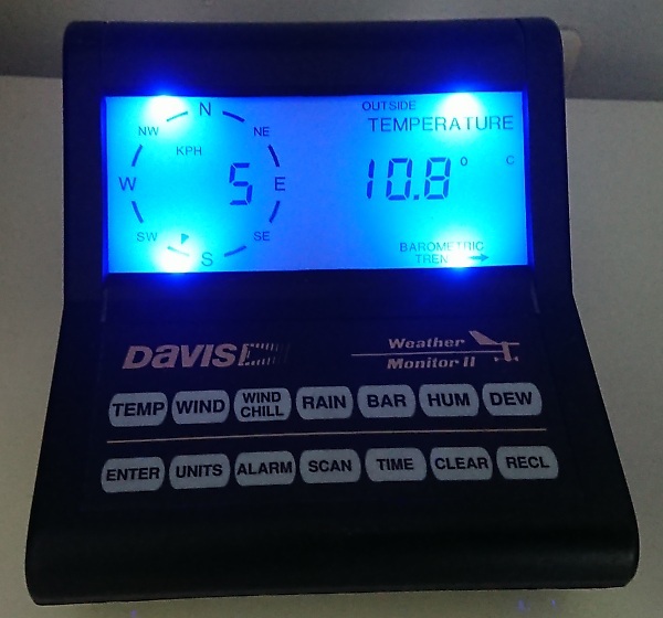
Replacing display lights on Weather Monitor II console
The old fashioned filament bulbs were replaced by LEDS, which as well avoids heating the interior of casing and (as DAVIS points out) induces errors in temperature reading by up to 0,5 °C.
Additional displays
Using MQTT subscription, it is off course possible to add more weather
displays ... including the barometric information of BME-280, RTC time
of max/min etc ...
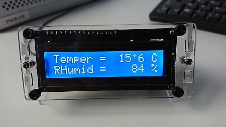
Compact display 2x16 with RTC clock (click for video)