
One of the two filters with it's relay switchbox. LEDs indicate operation on 80, 40 or 20m
Coax stub filters are useful to filter out harmonics generated by transceivers / power amplifiers, these can be used effectively when running a multi contest station, with antenna's in vicinity of each other.
They will attenuate harmonics, typically of the 'running' station - which is generally operating on the lower bands, while the multiplier is chasing DX on the higher bands. Harmonics will be attenuated to such level that the RX of the multiplier station is not overloaded in a manner that operation on the band is hampered, but not to such extent that operation is possible exactly on the harmonic frequency ...
As the filters are very 'sharp', in practice two filters (one for CW, the other for SSB band portion) should be put in series to cover the entire band and produce a good rejection on harmonics. You can expect about 25 dB attenuation (peak) per filter on the first harmonic ( 2f ), by putting 2 filters slightly off frequency in series you cannot expect 50 dB total attenuation, but in practice about 40dB.... However, by choosing a coax line of adequate length (multiples of λ/4) between PA, first filter, and second filter, additional attenuation is possible, resulting in some case up to 75dB total attenuation !
In addition to the coax stub filter placed between TRX / PA and antenna's, it is desirable to insert as well a band pass filter between TRX and PA - this to protect the receiver of the 'running' station against interference from the multiplier station transmissions. Both filter sets can then be automatically switched in function of the band on which the station is operating (using CAT or band voltage output).
One of the two filters with it's relay switchbox. LEDs indicate operation on
80, 40 or 20m
Hereby some measurements carried out with Keysight Fieldfox VNA, for both filters (CW & SSB, 80-40-20m) put in series, interconnected by a length of 2m65 coax (this is the ELECTRICAL length, not the physical ... and this length is quite optimal for cascading the filters)

SWR from 80m to 10m band, all filters OFF (raising on high end due to
switchboxes, relays, ...)
Transmitting on 80m band
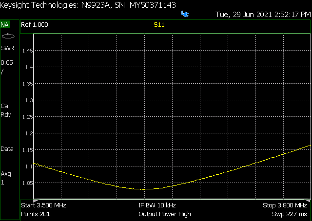
SWR with 80m harmonics filters active

Attenuation with 80m harmonics filters active

Attenuation of 80m 2nd harmonics on 40m band

Attenuation of 80m 3rd harmonics on 20m band

Attenuation of 80m 4th harmonics on 15m band

Attenuation of 80m 5th harmonics on 10m band (in practice, not very important
...)
Transmitting on 40m band
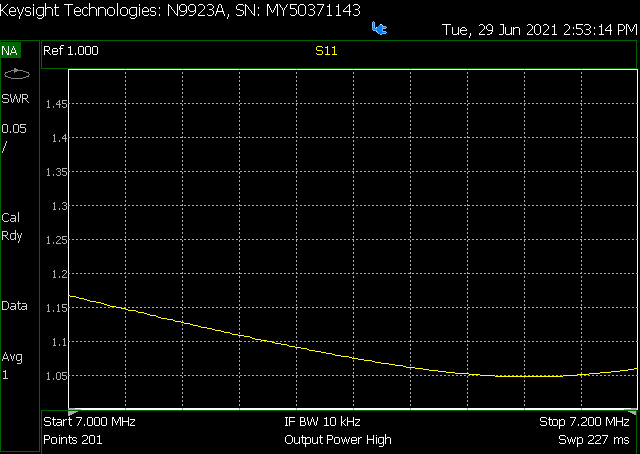
SWR with 40m filters active

Attenuation with 40m harmonics filters active

Attenuation of 40m 2nd harmonics on 20m band ( = very effective and useful )

Attenuation of 40m 3rd harmonics on 15m band ( = extremely effective and
useful )

Attenuation of 40m 4th harmonics on 10m band
Transmitting on 20m band
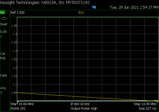
SWR with 20m filters active

Attenuation with 20m harmonics filters active

Attenuation of 20m 2nd harmonics on 10m band ( = very effective and useful )