Another ARDUINO based antenna rotor controller (AZ only)
Project presentation
Being interested in sporadic-E (Es) propagation on
4 and 6m bands, I was looking for a possibility to control in azimuth my
small YAGI antenna rotor (KENPRO / YAESU G400 type, with AC motor and no
brake, stop in the NORTH) automatically, in particular from WSJT & N1MM software. (Note :
if you are looking for AZ & EL control, see my other
controller here).
For controller with stop in SOUTH, I have as well a sketch which
needs to be tested - please contact me for details !
However WSJT does not offer a possibility to control
directly an antenna rotors, but 'PstRotator' software does - see
http://www.pstrotator.com by monitoring a 'status file'
generated by WSJT during QSO's.
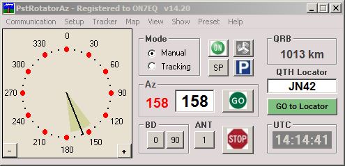
A simple display is more than enough for my basic needs
...
This software can be considered as the 'Swiss army knife'
to control almost any existing rotor and interface to almost any software
... it was developed by Codrut YO3DMU and is offered at a very
reasonable cost..
As I absolutely wanted to keep the existing control box,
an 'add-on' interface between PstRotator and the control box had to be
considered.
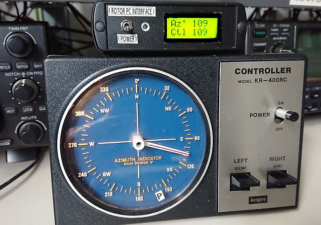
The controller interface on top of the original control
box
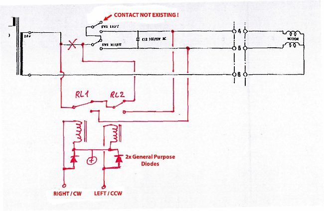
First of all, 2 relays were provided in cascade to
the 'LEFT' and 'RIGHT' switches of front panel, in such manner that the
automatic control can give opposite commands to the manual switches, but by
no means it is possible to have the motor rotating left & right
simultaneously ;o). There is plenty room left in the control box
cabinet for adding the relays.
See schematic of mods below.
Then some DC voltage reflecting the antenna position must
be taken from the box. This voltage must be varying - for a good readout
accuracy - 'as much as possible' between azimuth 000° and 359°, but by no
means go into negative polarity ... or additional circuits would be
necessary. Ideally, it should vary between approx +1V and + 4V against
control circuit 'ground' (in my case : the center tap of mains transformer).
Now, regarding to the ARDUINO sketch, there are several
possibilities published on the web. The most complete solution is certainly
proposed by K3NG, but for my purpose probably far to complicated to configure and put
into operation, the sketch being as well too elaborated to modify for my simple
requirements ...
I found another solution proposed by Viorel YO3RAK -
see information here . This sketch was more 'straightforward' and
well documented to dig into it and consider as a good starting point ... not
wanting to reinvent the wheel.
Specific functional requirements
The sketch written by Viorel is for 'EasyComm2'
protocol, however PstRotator software (maybe in version 'Azimuth only' ?) can
apparently only handle 'EasyComm1' protocol, which does not support
interrogation of actual antenna position and display on screen - it can only give commands
... a pity :o(.
Therefore, I changed communication protocol to YAESU
GS23,
GS-232A and GS-232B which supports bi-directional data exchange, and is widely spread.
Only the basic commands were implemented, as per PstRotator functional
features (this is : 'go to azimuth XXX, read and return actual
azimuth, and STOP rotation)
The sketch was streamlined to eliminate all 'elevation'
matters, as only azimuth is considered, and read inputs from voltage instead
as from encoders.
Further refinements were added :
-
Viorel's sketch relies on
Serial.readString()
to capture data from the serial line (in
fact, by the on board Arduino UART). Nice and easy, but by default this
command has a timeout of 1 second, waiting for more incoming data ...
what means that incoming data (like antenna position commands or antenna
position requests) can only be read and processed at most once per second. It is
desirable to have a more regular data flow, this is possible by
declaring an appropriate timeout. I used
'Serial.setTimeout(50)' which will provide 50ms timeout....
and now PstRotator can handle data exchange (and update it's display)
every 0,5s ! For other software, it might be required to increase
the timeout somewhat ...
-
In my simple rotator, there are no limit
switches... so I have provided 2 'failsafe' conditions :
-
my rotator turns the complete 360° in
1 minute and 10 seconds.... if the rotor motor is running continuously
during 1minute and 15seconds, there must be something really wrong ! In this
case, motor is powered off, and an ERROR is generated and the automatic
tracking is completely disabled ! Investigate problem and reset
with a power switch cycle ...
-
if a rotation command is issued,
but Arduino does subsequentially not detect any azimuth change, there must
be something wrong - maybe the antenna or motor are stuck or stalled ?
In this
case, motor is powered OFF and an ERROR is generated, and automatic tracking
is disabled !
-
In automatic tracking mode, once the
antenna has reached the requested target position, it can be manually further adjusted
with control box switches. Once the target position is reached, you are back
into 'manual' mode, so Arduino will not attempt to keep / hold the target position...
-
The DC output voltage from the control box corresponding
to antenna position did not seem to be completely linear ... therefore,
interpolation was required between 8 cardinal directions, more than enough
to have a good match between Arduino LCD / PstRotator readouts and the moving
pointer on the control box.
-
In case the rotor is running, and the
rotation sense is to be reversed, there is 'dead time' of 500ms provided to
allow the motor to effectively stop before being reversed.
-
A LED is indicating by short flashes the serial data
activity
-
A buzzer will signal commands received and
errors (e.g. motor stall, controller not powered, ...)
-
In PstRotator software, a 'PARK' command can
be issued. This will park the rotor in a pre-defined azimuth. The disadvantage
in this case is that the rotor pinions will start to wear and tear at same
position, due to effect of wind 'playing' with antenna.... The sketch
has a feature where the 'PARK' command is detected and rotor is sent to a
position + or - some random degrees around the preset value in PstRotator.
It will acknowledge the command showing 'PRK' then after 2 seconds the azimuth
to which rotor will be parked. The 'parking band' can be adjusted as a
parameter, here iit is defined as + and - 10° around the nominal park value set
in in PstRotator.
The Arduino Nano board and 2x8 character
LCD display are easily integrated in a small project box.
Schematic diagram
The project was realized with an ARDUINO Nano board,
offering the advantage of being flashable by USB port. On this same USB
port, you can connect your PC where the control software (PstRotator or
other ...) is running.
Instead of applying power to Arduino NANO via the 'VIN
pin', better provide a µA7805 voltage regulator which will as well power the
LCD display. As the backlight consumes about 50 mA, it is required to mount
the voltage regulator on the project box casing to provide some cooling.
IMPORTANT : it is absolutely necessary to
protect the analog input of Arduino against a negative voltage and/or a
level higher than +5 V ! Even if your potentiometer does
'normally' produce a voltage within range, what happens when the control box
is not connected to rotor .... or a potmeter becomes defective ??? See the 2
diodes provided for the protection.
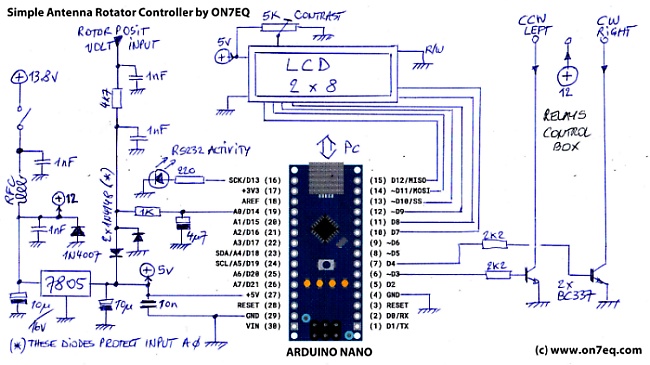
Note : a buzzer was added at a later stage. it is a piezo buzzer, powered
from the +5V line, a BC547 (small signal NPN) transistor acts as driver,
it's base connected by a 4k7 resistor to Arduino digital pin 6 - this is not
drawn on above schematic diagram.
Arduino sketch
The original sketch was modified while not looking into
crunching program code lines, as there is plenty room available in the
Arduino.... The sketch was developed for controllers with stop in the
NORTH - as usual for satellite tracking, EME etc. For controller with
stop in SOUTH, I have as well a sketch in Beta version - where
stop in N or S is defined as a parameter - and still needs to be
tested - please contact me for details !
Below is the sketch or
download it here.
It was compiled with IDE version 1.8.13 - IMPORTANT : Should you get errors when compiling,
use the same version of IDE ! You still can
download previous versions from ARDUINO website .
IMPORTANT: Please note that the software & device concept
is presented 'as is' with no guarantees whatsoever and can be used free of
license cost by individual HAMs, but not used for any commercial
purpose, as the intellectual property remains entirely by the author.
/* AZ/EL Antenna Rotator controller for Arduino - DC motors
* ========================================================
* Uses EasyComm protocol for computer - Tracking Software
* Manual command by means of two rotary encoders AZ - EL
*
* Viorel Racoviteannu
* https://www.youtube.com/channel/UCiRLZX0bV9rS04BGAyUf-fA
* https://racov.ro
* [email protected]
*
* I cannot take any responsibility for missuse of this code
* or any kind of damage it may occur from using this code.
*
* dec 2020 v2 - improved serial comm stability
* january 2021 - improved near target dead-zone, for which antenna won't move
* apr 2021 - improved serial comm stability
* jun 2021 - error proportional power for tracking movement
*
*/
////////////// UPPER USB = COM 16 CH340 //////////////////////
////////////// DELL PC LEFT USB COM 12 //////////////////////
/// VERSION HISTORY :
// V4 : implement interpolation between 8 ref positions
// V5 : limit motor running time to 1min15 = 75000 ms = OK
// V6 : stall detect , AZ not changing
// V7 : manual / software control mode + OK !
// V8 : LCD parallel
// STOP command software
// V9 : finetuning
// V10 : CW / CCW cast difference
// V11 : ERR display
// V12 : 27-02-2022: 500ms delay if motor direction is reversed while running
// V13 : Buzzer for error alert
// V14 : Random parking to avoid wear of pinions
/* // FOR I2C LCD
#include <Wire.h> // Library for I2C communication
#include <LiquidCrystal_I2C.h> // https://www.arduinolibraries.info/libraries/liquid-crystal-i2-c (Library for LCD)
// Wiring: SDA pin is connected to A4 and SCL pin to A5.
// Connect to LCD via I2C, default address 0x27 (A0-A2 not jumpered)
LiquidCrystal_I2C lcd(0x27, 8, 2); // address, chars, rows.
*/
// FOR PARALLEL LCD
#include <LiquidCrystal.h>
LiquidCrystal lcd(7, 8, 9, 10, 11, 12);
/* ***** for EA DIPS082 DISPLAY 2x 8 ******
*
*
* LCD RS pin 4 to digital pin 7
* LCD R/W pin 5 - put to GND
* LCD Enable pin 6 to digital pin 8
* LCD D4 pin 11 to digital pin 9
* LCD D5 pin 12 to digital pin 10
* LCD D6 pin 13 to digital pin 11
* LCD D7 pin 14 to digital pin 12
*
* LCD pin 1 = GND
* LCD pin 2 = + 5v 80 mA
* LCD pin 3 = contrast adjust), or adjust between 0 ... 5v by trimmer
*
*
*/
#include <SoftwareSerial.h>
/***********************************THIS IS WHERE YOU REALY TWEAK THE ANTENNA MOVEMENT***************/
// ANTENNA potentiometers CALIBRATION (counts)
#define Az000 213 //begining of the potentiometer (000°)
#define Az045 321
#define Az090 430
#define Az135 525
#define Az180 614
#define Az225 697
#define Az270 770
#define Az315 840
#define Az360 902 //end of the potentiometer
// ************ ROTOR PARAMETERS ************************************************************
// Allowed error for which antennna won't move. Minimum 1 degree
int AzErr = 15;
// Angle difference where soft stop begins (for casting motor)
int Amax_CW = 2; // clockwise / right
int Amax_CCW = 0; // counter clockwise / right
// max running time of rotor motor 1min15s
long unsigned MotorRunTimeLimit = 75000 ;
// max time motor can run if nu azimuth change detected (system stall)
int StallTimer = 5000 ;
// For PstRotator : Random parking band definition - e.g. '20' means + and - 10° around park set point in PstRotator
int ParkBand = 20 ; // Set to zero to disable this function. Must be < than 2x AzErr !
// ***********************************************************************************************
// other variables
#define AzPotPin A0 // select the input pin for the azim. potentiometer
#define AzRotPin_CCW 3 // select the out pin for rotation direction
#define AzRotPin_CW 4 // select the out pin for rotation direction
#define RS232pin 13 // RS-232 activity blinker
#define BuzzerPin (6) // pin for buzzer
bool SoftControl = false; // if controlled by software commands = true
int TruAzim = 0; // calculated real azimuth value
int ComAzim = 0; // commanded azimuth value
int RepAzim = 0; // reported Azimuth to software
int RawAzim = 0; // for interpolation
int OldTruAzim = 0; // to store previous azimuth value
int OldComAzim = 0;
char AzDir; // symbol for azim rot display
// flags for AZ tolerances
bool AzStop = false; // not used !!!!
bool rotate = false; // 'rotate command' active
bool rotate_CW = true; // flag rotate CW
//averaging loop
const int numReadings = 5; // averages the reading
int readIndex = 0; // the index of the current reading
int azimuth[numReadings]; // the readings from the analog input
int totalAz = 0; // the running total
long unsigned LastDispUpdate; // display update frequency
long unsigned LastBuzzer; // Buzzer sounding
long unsigned AzimChangeTime; // change of true azim detected
long unsigned MotorStartTime; // start of motor
long unsigned MotorStopTime; // stop of motor
bool MotorErr = false;
bool OFF = false; // when rotor command box is OFF = true
// variables for serial comm
String Azimuth = "";
String Elevation = "";
String ComputerRead;
String ComputerWrite;
long unsigned LastSerExch;
long unsigned StopCmdTime;
bool StopPrinted = false;
// build LCD specific characters 'degree'
byte degree [8] = {
B00100,
B01010,
B00100,
B00000,
B00000,
B00000,
B00000,
B00000,
};
// build LCD specific characters 'right'
byte right [8] = {
0b01000,
0b01100,
0b01110,
0b11111,
0b11111,
0b01110,
0b01100,
0b01000
};
// build LCD specific characters 'left'
byte left [8] = {
0b00010,
0b00110,
0b01110,
0b11111,
0b11111,
0b01110,
0b00110,
0b00010
};
////////////////////////////////////////////////////
//////////////////// S E T U P ///////////////////
////////////////////////////////////////////////////
void setup() {
Serial.begin(9600);
Serial.setTimeout(50); // sets the maximum milliseconds to wait for serial data. It defaults to 1000 milliseconds
// too long for PST rotator updates ...
// FOR PARALLEL LCD
//
// Initiate the LCD: 8 char x 2 rows
lcd.begin(8,2);
//
/* Initiate the I2C LCD:
lcd.init();
lcd.backlight();
*/
lcd.createChar(1, degree);
lcd.createChar(2, right);
lcd.createChar(3, left);
// pin declaration
digitalWrite(AzRotPin_CCW, LOW); // deactivate rotation pin left
digitalWrite(AzRotPin_CW, LOW); // deactivate rotation pin right
digitalWrite(RS232pin, LOW); // RS232pin
pinMode(AzRotPin_CCW, OUTPUT); //declaring azim. rotation direction Pin as OUTPUT
pinMode(AzRotPin_CW, OUTPUT); //declaring azim. rotation direction Pin as OUTPUT
pinMode(RS232pin, OUTPUT);
pinMode(AzPotPin, INPUT);
pinMode(BuzzerPin, OUTPUT);
// write on display name and version
lcd.clear();
lcd.setCursor(0, 0); // Set the cursor on the first column first row.(counting starts at 0!)
lcd.print("RotorCTL");
lcd.setCursor(0, 1); // Set the cursor on the first column the second row
lcd.print("V4 04-24");
/*
tone(BuzzerPin,2100);
delay (250);
tone(BuzzerPin,2300);
delay (250);
*/
tone(BuzzerPin,2400,250); // Frequency, duration
//delay (250);
//noTone (BuzzerPin);
delay(1500); // keep for 1.5 seconds
lcd.clear();
lcd.setCursor(0, 0); // Set the cursor on the first column first row.(counting starts at 0!)
lcd.print(" by ");
lcd.setCursor(0, 1); // Set the cursor on the first column the second row
lcd.print(" ON7EQ");
delay(1500); // keep for 1.5 seconds
lcd.clear();
lcd.setCursor(0, 0); // Set the cursor on the first column first row.(counting starts at 0!)
lcd.print(" YAESU");
lcd.setCursor(0, 1); // Set the cursor on the first column the second row
lcd.print(" 9k6");
delay(1500); // keep for 1.5 seconds
lcd.clear();
// display Azim. value
lcd.setCursor(0, 0);
lcd.print("Az --- ");
lcd.setCursor(2, 0);
lcd.write(1);
lcd.setCursor(0, 1);
lcd.print("Ctl --- ");
// this is to set azim-command the same value as real, not to jerk the antenna at start-up
RawAzim = analogRead(AzPotPin);
if ( (RawAzim <= Az045)) TruAzim = (map(RawAzim, Az000, Az045, 0, 45));
if ((RawAzim > Az045) and (RawAzim <= Az090)) TruAzim = (map(RawAzim, Az045, Az090, 45, 90));
if ((RawAzim > Az090) and (RawAzim <= Az135)) TruAzim = (map(RawAzim, Az090, Az135, 90, 135));
if ((RawAzim > Az135) and (RawAzim <= Az180)) TruAzim = (map(RawAzim, Az135, Az180, 135, 180));
if ((RawAzim > Az180) and (RawAzim <= Az225)) TruAzim = (map(RawAzim, Az180, Az225, 180, 225));
if ((RawAzim > Az225) and (RawAzim <= Az270)) TruAzim = (map(RawAzim, Az225, Az270, 225, 270));
if ((RawAzim > Az270) and (RawAzim <= Az315)) TruAzim = (map(RawAzim, Az270, Az315, 270, 315));
if ((RawAzim > Az315) ) TruAzim = (map(RawAzim, Az315, Az360, 315, 359));
//TruAzim = (map(analogRead(AzPotPin), AzMin, AzMax, 0, 359)); // azimuth value 0-359 , for linear pot
if (TruAzim<0) {TruAzim=0;}
if (TruAzim>359) {TruAzim=359;} // keep values between limits
// initialize all the readings
for (int thisReading = 0; thisReading < numReadings; thisReading++) {
azimuth[thisReading] = 0;
}
ComAzim = TruAzim;
OldTruAzim = TruAzim;
OldComAzim = ComAzim;
DisplTruAzim();
DisplComAzim();
AzimChangeTime = millis ();
LastBuzzer = millis();
randomSeed(analogRead(AzPotPin)); // generate random for parking
if (ParkBand > (2 * AzErr)) ParkBand = 2 * AzErr; // ParkBand can't be > than 2x AzErr !
}
////////////////////////////////////////////////////
////////////////////// L O O P /////////////////////
////////////////////////////////////////////////////
void loop() {
// Sound buzzer for motor error
if ((millis() - LastBuzzer > 2000) and (MotorErr == true)) {
tone(BuzzerPin,2400,500); // Frequency, duration
//delay (500);
//noTone (BuzzerPin);
LastBuzzer = millis();
}
// AZIMUTH AVERAGING LOOP
totalAz = totalAz - azimuth[readIndex];
// read from the sensor:
RawAzim = analogRead(AzPotPin);
if (RawAzim < 150 ) { // detect if CONTROLLER is powered
OFF = true;
}
else OFF = false;
if ( (RawAzim <= Az045)) azimuth[readIndex] = (map(RawAzim, Az000, Az045, 0, 45));
if ((RawAzim > Az045) and (RawAzim <= Az090)) azimuth[readIndex] = (map(RawAzim, Az045, Az090, 45, 90));
if ((RawAzim > Az090) and (RawAzim <= Az135)) azimuth[readIndex] = (map(RawAzim, Az090, Az135, 90, 135));
if ((RawAzim > Az135) and (RawAzim <= Az180)) azimuth[readIndex] = (map(RawAzim, Az135, Az180, 135, 180));
if ((RawAzim > Az180) and (RawAzim <= Az225)) azimuth[readIndex] = (map(RawAzim, Az180, Az225, 180, 225));
if ((RawAzim > Az225) and (RawAzim <= Az270)) azimuth[readIndex] = (map(RawAzim, Az225, Az270, 225, 270));
if ((RawAzim > Az270) and (RawAzim <= Az315)) azimuth[readIndex] = (map(RawAzim, Az270, Az315, 270, 315));
if ((RawAzim > Az315) ) azimuth[readIndex] = (map(RawAzim, Az315, Az360, 315, 359));
//azimuth[readIndex] = (map(analogRead(AzPotPin), Az000, Az360, 0, 359)); /// For linear pot
// add the reading to the total:
totalAz = totalAz + azimuth[readIndex];
// advance to the next position in the array:
readIndex = readIndex + 1;
// if we're at the end of the array, wrap around to the beginning:
if (readIndex >= numReadings) {readIndex = 0;}
// calculate the average:
TruAzim = totalAz / numReadings;
if (TruAzim<0) {TruAzim=0;}
if (TruAzim>359) {TruAzim=359;} // keep values between limits
// update antenna true position display
if ((millis()- LastDispUpdate) > 100){ //not to flicker the display
LastDispUpdate = millis();
/*
if (RawAzim < 150 ) {
lcd.setCursor(4, 0);
lcd.print ("OFF");
OFF = true;
}
*/
if (OFF == true) {
lcd.setCursor(4, 0);
lcd.print ("OFF");
}
else if (abs(OldTruAzim - TruAzim)>1 ) { // eliminate last digit jitter in display and PC software
AzimChangeTime = millis(); //reset azimuth change timer
DisplTruAzim();
RepAzim = TruAzim;
}
}
if ( (millis() - AzimChangeTime > StallTimer) and (rotate == true)) { // Check for motor stall
MotorErr = true; //No AZ change during > stalltimer while rotate command active --> ERROR !
digitalWrite(AzRotPin_CCW, LOW); // deactivate rotation pin left
digitalWrite(AzRotPin_CW, LOW); // deactivate rotation pin right
lcd.setCursor(3, 0);
lcd.print(" ");
lcd.setCursor(7, 0);
lcd.print(" ");
lcd.setCursor(4, 1);
lcd.print("ERR");
}
// every 0,1 seconds looking for serial communication
if ((millis()- LastSerExch) > 100){
digitalWrite(RS232pin, LOW);
LastSerExch = millis();
if (Serial.available() > 0) {
digitalWrite(RS232pin, HIGH); // blink LED
SerComm();
}
}
// update command target position display
if (ComAzim != OldComAzim) {
SoftControl = true; // we have received a command from software
AzimChangeTime = millis () ; // reset AZ change timer, keep before rotating antenna
DisplComAzim();
}
// this is to rotate in azimuth
if (TruAzim == ComAzim) { // if equal, stop moving
digitalWrite(AzRotPin_CCW, LOW); // deactivate rotation pin left
digitalWrite(AzRotPin_CW, LOW); // deactivate rotation pin right
rotate = false; // AzMotor stopped
SoftControl = false; // back to manual mode
lcd.setCursor(3, 0);
lcd.print(" ");
lcd.setCursor(7, 0);
lcd.print(" ");
lcd.setCursor(4, 1);
if (MotorErr == false) {
lcd.print(" - ");
}
}
/*
else if ((abs(ComAzim-TruAzim) <= Amax)) { // uitloop motor, STOP !
digitalWrite(AzRotPin_CCW, LOW); // deactivate rotation pin left
digitalWrite(AzRotPin_CW, LOW); // deactivate rotation pin right
rotate = false; // AzMotor stopped
SoftControl = false ; // back to manual mode
lcd.setCursor(3, 0);
lcd.print(" ");
lcd.setCursor(7, 0);
lcd.print(" ");
}
*/
else if ((abs(ComAzim-TruAzim) <= Amax_CW) and (rotate_CW == true)) { // uitloop motor, STOP !
digitalWrite(AzRotPin_CCW, LOW); // deactivate rotation pin left
digitalWrite(AzRotPin_CW, LOW); // deactivate rotation pin right
rotate = false; // AzMotor stopped
SoftControl = false ; // back to manual mode
lcd.setCursor(3, 0);
lcd.print(" ");
lcd.setCursor(7, 0);
lcd.print(" ");
lcd.setCursor(4, 1);
if (MotorErr == false) {
lcd.print(" - ");
}
}
else if ((abs(ComAzim-TruAzim) <= Amax_CCW) and (rotate_CW == false)) { // uitloop motor, STOP !
digitalWrite(AzRotPin_CCW, LOW); // deactivate rotation pin left
digitalWrite(AzRotPin_CW, LOW); // deactivate rotation pin right
rotate = false; // AzMotor stopped
SoftControl = false ; // back to manual mode
lcd.setCursor(3, 0);
lcd.print(" ");
lcd.setCursor(7, 0);
lcd.print(" ");
lcd.setCursor(4, 1);
if (MotorErr == false) {
lcd.print(" - ");
}
}
else if ((abs(TruAzim - ComAzim)<=AzErr)&&(rotate == true) && (SoftControl == true)) { // if in tolerance, but it wasn't an equal, rotate
if (MotorErr == false) {
AzimRotate();
}
else { // MotorErr = true !
digitalWrite(AzRotPin_CCW, LOW); // we have motor error
digitalWrite(AzRotPin_CW, LOW); //
}
}
else if ((abs(TruAzim - ComAzim)>AzErr) && (SoftControl == true)){ // if target is off tolerance
if (MotorErr == false) {
AzimRotate(); // rotate
}
else { // MotorErr = true !
digitalWrite(AzRotPin_CCW, LOW); // we have motor error
digitalWrite(AzRotPin_CW, LOW); //
}
}
//// Clear STOP in display
if ((millis()- StopCmdTime > 3000) and (StopPrinted == true)) {
lcd.setCursor(4, 1);
lcd.print(" - ");
StopPrinted = false;
}
// delay(20); //pause the program for x ms
}
/////////////////////////////////////////////////////
////////////// procedures definitions //////////////
/////////////////////////////////////////////////////
//////// Display actual rotor azimuth ///////////
void DisplTruAzim() {
lcd.setCursor(4, 0);
if (TruAzim<10) {
lcd.print("00");
lcd.print(TruAzim);}
else if (TruAzim<100) {
lcd.print("0");
lcd.print(TruAzim);}
else {lcd.print(TruAzim);}
OldTruAzim = TruAzim;
// ************** FOR CALIBRATION PURPOSES **************
/*
lcd.setCursor(0, 1);
lcd.print (analogRead(AzPotPin));
lcd.print (" ") ;
*/
}
/////// Display command azimuth //////////////
void DisplComAzim(){
lcd.setCursor(4, 1);
if (ComAzim<10) {
lcd.print("00");
lcd.print(ComAzim);}
else if (ComAzim<100) {
lcd.print("0");
lcd.print(ComAzim);}
else {lcd.print(ComAzim);}
//lcd.print (String(char(223))); // degrees
OldComAzim = ComAzim;
//
}
////////// Rotate antenna //////////////////////
void AzimRotate() {
if (rotate == false ) MotorStartTime = millis();
if ((ComAzim-TruAzim) > (TruAzim-ComAzim)) { // this to determine direction of rotation
// ROTATE RIGHT - CW
if ((rotate == false ) and (MotorErr == false)) MotorStartTime = millis();
digitalWrite(AzRotPin_CCW, LOW); // deactivate rotation pin left
if ((rotate_CW == false) and (rotate == true)) delay (500); // allow time to treverse motor, if rotation inversed
if (millis() - MotorStartTime < MotorRunTimeLimit) {
if (MotorErr == false ) digitalWrite(AzRotPin_CW, HIGH); // rotate right
rotate = true;
rotate_CW = true;
AzimChangeTime = millis () ; // reset AZ change timer at start of rotation
AzDir = char(126);
} // "->"
else {
digitalWrite(AzRotPin_CW, LOW); // stop if running too long
lcd.setCursor(3, 0);
lcd.print(" ");
lcd.setCursor(7, 0);
lcd.print(" ");
lcd.setCursor(4, 1);
lcd.print("ERR");
MotorErr = true;
}
}
else {
// ROTATE LEFT - CCW
if ((rotate == false ) and (MotorErr == false)) MotorStartTime = millis();
digitalWrite(AzRotPin_CW, LOW); // deactivate rotation pin right
if ((rotate_CW == true) and (rotate == true)) delay (500); // allow time to treverse motor, if rotation inversed
if (millis() - MotorStartTime < MotorRunTimeLimit) {
if (MotorErr == false ) digitalWrite(AzRotPin_CCW, HIGH); // rotate left
rotate = true;
rotate_CW = false;
AzimChangeTime = millis () ; // reset AZ change timer at start of rotation
AzDir = char(127);
} // "<-"
else {
digitalWrite(AzRotPin_CCW, LOW); // stop if running too long
lcd.setCursor(3, 0);
lcd.print(" ");
lcd.setCursor(7, 0);
lcd.print(" ");
lcd.setCursor(4, 1);
lcd.print("ERR");
MotorErr = true;
}
}
// Print direction arrows
if (AzDir == char(126)) { //CW or turning right
lcd.setCursor(3, 0);
lcd.print(" ");
lcd.setCursor(7, 0);
//lcd.print(String(AzDir));
lcd.write(2);
}
if (AzDir == char(127)) { //CCW or turning left
lcd.setCursor(7, 0);
lcd.print(" ");
lcd.setCursor(3, 0);
//lcd.print(String(AzDir));
lcd.write(3);
}
}
///////// Handle serial communication /////////////
void SerComm() {
// initialize readings
ComputerRead = "";
Azimuth = "";
while(Serial.available()) {
ComputerRead= Serial.readString(); // read the incoming data as string (in this case, default timeout = 1 sec unless declared)
// Serial.println(ComputerRead); // echo the reception for testing purposes
}
// looking for command : YAESU style : Mxxx = Move to azimuth XXX
for (int i = 0; i <= ComputerRead.length(); i++) {
if ((ComputerRead.charAt(i) == 'M') and (MotorErr == 0)){ // if read AZIMUTH command
for (int j = i+1; j <= ComputerRead.length(); j++) {
if (isDigit(ComputerRead.charAt(j))) { // if the character is number
Azimuth = Azimuth + ComputerRead.charAt(j);
}
else {break;}
}
}
if (ComputerRead.charAt(i) == 'S'){ // if read STOP command
SoftControl = false; // halt software control
rotate = false; // interrupts rotate command
digitalWrite(AzRotPin_CCW, LOW); // deactivate rotation pin left
digitalWrite(AzRotPin_CW, LOW); // deactivate rotation pin right
MotorErr = false; // manual reset of motor error condition
lcd.setCursor(3, 0);
lcd.print(" ");
lcd.setCursor(7, 0);
lcd.print(" ");
lcd.setCursor(4, 1);
lcd.print("STP");
StopPrinted = true;
StopCmdTime = millis();
tone(BuzzerPin,2400,150); // Frequency, duration
}
}
// if <AZxx> received
if (Azimuth != ""){
ComAzim = Azimuth.toInt();
// if PARK command issued from PSTrotator : First STOP, immediately followed by MOVE
if (millis() - StopCmdTime < 500) {
ComAzim = ComAzim - ParkBand/2 ; // park position within Park Band
ComAzim = ComAzim + random(0,ParkBand+1);
}
ComAzim = (ComAzim+360)%360; // keeping values between limits
if (OFF == false) {
tone(BuzzerPin,2400,30); // Frequency, duration
}
else {
tone(BuzzerPin,2400,30); // Frequency, duration
delay (80);
tone(BuzzerPin,2400,30); // Frequency, duration
delay (80);
tone(BuzzerPin,2400,30); // Frequency, duration
}
}
// looking for <AZ> interogation for antenna position / YAESU protocol = 'C' reply is +0xxx xxx = azimuth
for (int i = 0; i <= (ComputerRead.length()); i++) {
if ((ComputerRead.charAt(i) == 'C') and (millis() > 6000) ){ /// give some time to average position, so PstRotataor indicates set AZ as actual AZ
// send back the antenna position <+0xxx>
ComputerWrite = "+0"+String(RepAzim);
Serial.println(ComputerWrite);
}
}
}