This sketch will synchronize (in so called 'satellite mode') 2 YAESU transceivers, like FT-817, FT-857, FT-897, ...for operation in full duplex on QO-100 (Es'hail SAT) narrowband transponder.
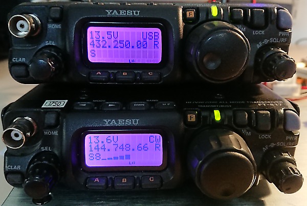
It was developed for a very compact portable QO-100 station, based on two FT-817 transceivers, the uplink being on 432 MHz, the downlink on 144 MHz - but this can be easily changed according to your needs in the sketch. Even the satellite frequencies can be changed, should this be required.
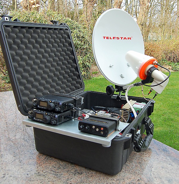
ON7EQ QO-100 portable station with 35 cm dish, all stowed in PELICAN
transport case
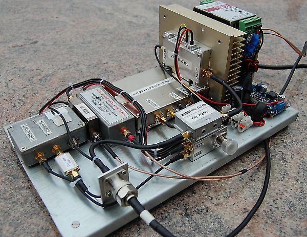
The RF-deck (G0MRF converter, 25 MHz TCXO, SG-labs transverter and PA,
power supply)
The hardware
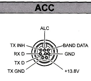
The hardware is composed by an ARDUINO Nano board, a 2x 16 LCD display, a piezo buzzer, and off course cables between the ACC socket of both RIGs and the Arduino microcontroller. For the cables to ACC socket, the most easy way is to purchase a 'mini DIN to mini DIN' cable and cut it in half. Apart from CAT control, Arduino can as well inhibit uplink transmission (using the 'TX_inhibit' pin of ACC jack) should this be desirable (e.g. attempting to transmit in FM, out of band, or on the beacon frequencies ...)
Two push buttons are required : one push button is used to cycle through different operating modes, the second one is used to 'set' or 'confirm' some values within each mode. The 'mode' push button connected to A0 pin of Arduino, the 'set' push button to A1 pin. Both analog input pins are pulled-up to +5v by a resistor (any value will do between 2k2 ... 22k), the push buttons will pull the inputs to GND.
A schematic diagram of components & interconnection can be downloaded here as pdf.
The sketch / interface will take care of following functions / operating modes, cycled in sequence :
-
Set up / configure both transceivers at startup, retrieve TX and RX offsets stored in EEPROM (see below)
-
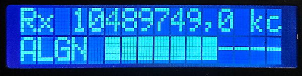
Assist in aiming the dish (DISH ALIGN MODE):
-
Set downlink receiver on the engineering beacon frequency and in CW mode (provides faster AGC response, desirable for S-meter response)
-
Display signal strength on a bargraph display + produce an audible beep, with increasing pitch for stronger signal
-
-
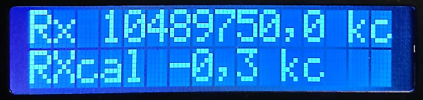
Calibrate the downlink chain for possible frequency offset (CALIBR. RX MODE) :
-
Will set downlink receiver on engineering beacon frequency
-
Twice per second, change operating mode from USB to LSB
-
Now, tune the receiver in order to hear the same beacon tone (warbling sound) in USB and LSB
-
Press the SET button to define RX offset and store value in EEPROM (it can off course be updated later, if required)
-
-
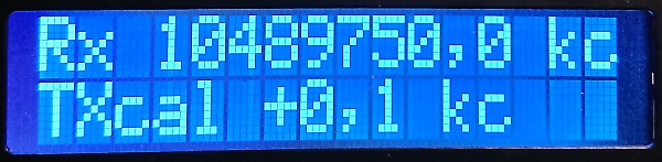
Calibrate the uplink chain for possible frequency offset (CALIBR. TX MODE):
-
Set downlink frequency on a free SSB frequency, the uplink will follow automatically
-
Now transmit, and while keeping the SET button depressed, adjust uplink frequency for 'zero beat' on the downlink
-
When the uplink signal is 'spot on' the downlink, release the SET button
-
Now TX offset is defined and value stored in EEPROM (it can off course be updated later, if required)
-
-
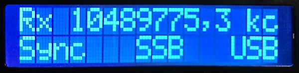
Run in full duplex, synchronized (SYNC MODE)
-
Uplink will follow downlink continuously for frequency and operating modes (USB, CW, DIG, ...)
-
Downlink frequency & operating mode will be displayed as well as recommended mode as per QO-100 bandplan
-
Uplink transmission will be inhibited for 'abnormal' conditions (out of band, on beacon frequency, ...)
-
-
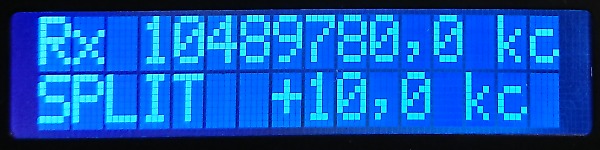
Run in SPLIT mode, chasing DX ('SPLIT Chasing DX' MODE):
-
Find the DX station downlink signal, it is displayed on LCD
-
Now keep the SET button depressed, and search for the frequency where the DX is listening by adjusting the RX VFO
-
Or, as SPLIT offset is shown, simply tune to the announced offset (e.g. '10 up')
-
Release the SET button. Now the receiver will return to the DX downlink frequency, while the UPLINK remains fixed.
-
You can adjust receive frequency, but UPLINK will remain fixed.
-
-
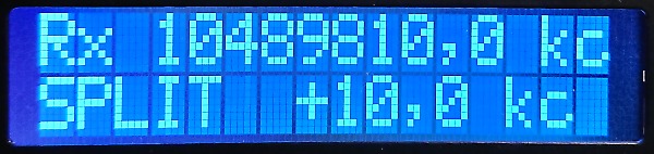
Run in SPLIT mode, we are the DX ('SPLIT we are DX' mode):
-
Find a free frequency where you will be transmitting, check if your intended SPLIT frequency is as well free
-
Now depress the SET button - you will be listening automatically 10 kHz higher ('10 up') - check if still free !
-
Adjust the downlink frequency, if you want another SPLIT than 10 kHz, or if you are listening '10 to 15 up' - the SPLIT offset is continuously displayed
-
Adjust receive VFO as required to work the pile-up, while the transmit frequency remains fixed.
-
-
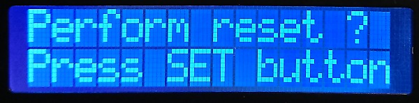
RESET / re-initialize mode ( 'Perform reset ?' mode)
-
if SET button is pressed long enough, it will revert to SET UP mode (like a 'cold start' of sketch)
-
if SET not pressed, it will cycle to 'SYNC' mode
-
The sketch
It has been more than 5 years since I have actively developed sketches for Arduino ... so it was a somewhat steep learning curve to start over - it is always amazing how fast some skills are fainting away !
Therefore, all coding used is very 'basic', and on the other hand the sketch is well commented.
No doubt the sketch could be streamlined in a more 'lean and mean' way ... and further debugging is sure required. But, the advantage of the sketch being coded in quite 'basic' manner is that is will be easily adapted by Arduino neophytes ;o)
All further modifications are 'at your own risk', and please don't ask me to debug your changes. All suggestions, and certainly improvements are mostly welcome to be shared with our HAM community !
The YAESU CAT library
The sketch relies on the 'FT897' library to interface with both transceivers and handle all communication in the YAESU '5 bytes format', it was developed by James Buck, VE3BUX (www.ve3bux.com) , extended by F6CZV Philippe, and finally ONL12523 Gilbert who allowed definition of multiple serial ports as a parameter. Thanks to all for great work and sharing ! Myself changed in 'FT897.cpp' two values of timeout parameters from 2000ms to 200ms, this speeds up startup of communications within the sketch, without noticing adverse effects...
To run this sketch, it is imperative to use the modified FT897 library (download it here), and not the original which will not allow multiple serial communication ports, as a parameter, but only hard-coded !
To install this library, simply unzip the file 'FT897.zip' in the 'libraries' folder of IDE, in order to create the folder 'FT897' with content files 'ft897.h' and 'ft897.cpp' .
Running multiple serial ports on Arduino (nano)
Running multiple serial ports on Arduino is tricky, as there is only the standard serial port on board (on D0/D1 pins) which is linked with an UART, who's task is to buffer TX and RX data while the sketch is running in 'background'. (remark: Arduino MEGA boards have more UARTS, but board is much bigger in size ...)
Luckily, the library 'Softwareserial.h' can handle multiple serial ports, but limitation is that it is able to listen only to one port at the time - this because the serial receive process is interrupt driven. This implies that the relevant port must first be declared on which some data is expected before it can be decoded. It was not very easy to implement the serial communication to the two transceivers in this way, sometimes very odd and unexpected results were noted, but after a lot of 'trial and error' it seems to work fine ...
Below is the sketch or download it here. It was compiled with IDE version 1.8.13. You can download the library FT897 (as zipped file) here.
Good luck and CU on QO-100 !
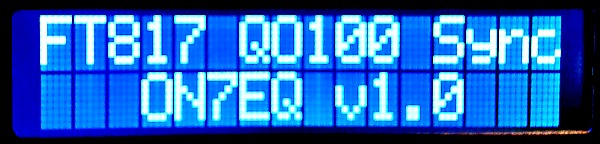
/* ************************************************************** * QO-100 SYNC for YAESU radio FT817 / FT897 / FT857 / ... * * Arduino NANO board and 2x16 char LCD display * * by ON7EQ March 2021 - www.on7eq.com * ************************************************************** Version 1.00 of 05 March 2021 Compiled with IDE v 1.8.13 for ARDUINO NANO board Developed for use with 2x FT817 transceivers, UPLINK transmitting on 432 MHz, DOWNLINK receiving on 144 Mhz But these parameters can be easily adapted in the constants, in fact even the satellite/frequency can be redefined ... Should work as well with FT897, FT857, ... all YAESU radio's using CAT commands which are contained in a 5 byte structure. */ //////////////////////// INCLUDE REQUIRED LIBARIES ///////////////////////////// #include <LiquidCrystal.h> LiquidCrystal lcd(12, 11, 10, 9, 8, 7); /* * LCD RS pin to digital pin 7 * LCD Enable pin to digital pin 8 * LCD D4 pin to digital pin 9 * LCD D5 pin to digital pin 10 * LCD D6 pin to digital pin 11 * LCD D7 pin to digital pin 12 * LCD R/W pin to ground * GND to LCD VO pin (pin 3) (contrast adjust), or adjust between 0 ... 5v by trimmer*/ #include <EEPROM.h> // required to store/extract values saved in EEPROM #include <SoftwareSerial.h> #include "FT897.h" // based on the work of James Buck, VE3BUX Web: http://www.ve3bux.com // library modified by ONL12523 Gilbert to allow definition of multiple IO lines - use this instead of original by VE3BUX // to install library, simply create the folder 'FT897' in the 'libraries' folder of IDE and save 'ft897.h' and 'ft897.cpp' in this folder // many thanks to Jim and Gil for your work and sharing it with us ! FT897 uplink_radio; // define "uplink_radio" so that we may pass CAT commands - uplink is 432 MHz FT897 downlink_radio; // define "downlink_radio" so that we may pass CAT commands - downlink is 144 MHz /// CAT connection to ARDUINO // Connect RX pin Arduino to TX_D terminal of ACC socket, TX pin to RX_D terminal of ACC socket // Insert 3k3 resistor in both lines for protection. SoftwareSerial uplink_radio_serial (2, 3); //// (RX,TX) SoftwareSerial downlink_radio_serial (4, 5); //// (RX,TX) //////////////////////////////////////////// ////////// DEFINE KEY VARIABLES /////////// //////////////////////////////////////////// #define uplinkradio_baudrate (9600) // Set baudrate for uplink CAT here, tested with FT817 on 9k6 = OK ! #define downlinkradio_baudrate (9600) // Set baudrate for downlink CAT here, tested with FT817 on 9k6 = OK ! #define QRG_TXuplink (43225000) // Uplink transmitter NOMINAL QRG to transmit on top of SAT beacon, expressed in "10 Hz" multiple long act_QRG_TXuplink = 43225000; // Actual Uplink QRG on transmitter long uplink_offset = 0; // Uplink offset, expressed in "10 Hz" multiple long old_uplink_offset = 0; // Uplink offset, expressed in "10 Hz" multiple long QRG_uplink = 0; // Actual uplink frequency, on the TX uplink #define QRG_RXdownlink (14475000) // Corresponding receiver NOMINAL downlink QRG to receive SAT beacon, expressed in "10 Hz" multiple long act_QRG_RXdownlink = 14475000; // Actual Downlink QRG on receiver long downlink_offset = 0; // Downlink offset, expressed in "10 Hz" multiple long old_downlink_offset = 0; //Downlink offset, expressed in "10 Hz" multiple long QRG_DX_downlink = 0; // Actual SAT transponder effective & accurate/corrected receive frequency of DX station, expressed in "10 Hz" multiple long split_offset = 0; // Offset running split mode , 'DX listening UP' is positive #define QRG_beacon (1048975000) // SAT Engineering Beacon nominal Frequency long beacon_offset = 0; // Beacon offset, as perceived in downlink RX, expressed in "10 Hz" multiple long QRG_SAT_downlink = 0; // Actual SAT transponder effective & accurate receive frequency, expressed in "10 Hz" multiple #define SAT_xponder_delta (808950000) // SAT transponder NOMINAL difference (downlink-uplink) frequency, expressed in "10 Hz" multiple long LO_downconverter = 0; // Difference between NOMINAL SAT downlink and nominal downlink RX, value will be computed in sketch ... long UP_converterdelta = 0; // Difference between NOMINAL SAT uplink signal and nominal uplink TX, value will be computed in sketch . byte firstrun_align = 1; // first run of align routine byte op_mode_change = 1; // when op_mode is changed, set on '1' to start loop ! byte op_mode_button = 0; // When "Change operating mode" button pressed = 1 byte SET_button = 0; // while SET button is pressed is 1 byte SET_button_released = 0; // if SET button has just been released is '1' (required to put in EEPROM etc) byte SET_button_pressed = 0; // if SET button has just been pressed is '1' byte SET_button_pressed_once = 0; // if SET button was pressed once is '1' #define TonePin (6) // pin for piezo buzzer byte MSB; // MSB Most Significant byte byte LSB; int op_mode = 0; // Operating mode of sketch, cycled by depressing the 'mode' push button : // 0 = startup, initialise system // 1 = align dish // 2 = calibrate RX with beacon // 3 = calibrate TX, adjust uplink for 'zero beat' downlink // 4 = run synced UP- & DOWNlink // 5 = SPLIT - Chasing DX // 6 = SPLIT - we are DX ! // 7 = RESET, re-initilaise #define pin_mode_sw (A0) // 'mode select' pushbutton #define pin_SET_sw (A1) // 'set' pushbutton /// OPTION : inhibit uplink transmit #define UPL_TX_inh_pin (13) // when +5v = inhibited. Connect to YAESU ACC pin 'TX_INHIBIT' through 3k3 resistor for protection // TRX will go into transmit mode, but no RF power on output // Downlink transceiver ACC pin 'TX_INHIBIT' can be permanently set to +5V through 3k3 resistor for protection String S_meter_value = "ABCDEFG"; String downlink_radio_mode = "ABCD"; String downlink_radio_prev_mode = "EFGH"; ////////// Define custom LCD Characters /// // For bargraph S-meter byte Smeter[8] = { B11111, B11111, B11111, B11111, B11111, B11111, B11111, }; ////////// BANDPLAN QO-100 /////////////// #define CW_bcn (1048950000) #define CW_only (1048954000) #define NBD (1048958000) #define DIG (1048965000) #define SSB1 (1048974500) #define PSK_bcn (1048975500) #define SSB2 (1048985000) #define EMY (1048986000) #define MIX (1048999500) #define exp_bcn (1049000000) //////////////////////////////////////////////////////////// //////////////////// S E T U P ////////////////////////// //////////////////////////////////////////////////////////// void setup() { // Initialize digital out pins pinMode(UPL_TX_inh_pin, OUTPUT); pinMode(TonePin, OUTPUT); digitalWrite(UPL_TX_inh_pin, HIGH); /// Inhibit TX // Clear EEPROM contents /* // Uncomment if you need to clear EEPROM relevant cells, and run once EEPROM.write (0,0); EEPROM.write (1,0); EEPROM.write (2,0); EEPROM.write (3,0); EEPROM.write (4,0); EEPROM.write (5,0); */ tone(TonePin,2500); // emit beep at startup delay (200) ; noTone(TonePin); ////////// INITIALIZE SERIAL COMMS ///////////////////// // Serial for debug // not used in this sketch Serial.begin(9600); // Serial for UPLINK radio uplink_radio.setSerial(&uplink_radio_serial); uplink_radio.begin(uplinkradio_baudrate); // Set uplink transmitter parameters uplink_radio.setMode("USB"); uplink_radio.setFreq(QRG_TXuplink); // Serial for DOWNLINK radio downlink_radio.setSerial(&downlink_radio_serial); downlink_radio.begin(downlinkradio_baudrate); // Set downlink receiver parameters downlink_radio.setMode("USB"); downlink_radio.setFreq(QRG_RXdownlink); ////////// INITIALIZE LCD ///////////////////// // set up the LCD's number of columns and rows: lcd.begin(16, 2); lcd.clear(); // Create custom characters lcd.createChar(0, Smeter); // Bargraph S-meter // Print a message to the LCD. lcd.setCursor(0, 0); lcd.print("FT817 QO100 Sync"); lcd.setCursor(0, 1); lcd.print(" ON7EQ v1.0"); delay(1000); lcd.clear(); // Compute some variables LO_downconverter = QRG_beacon - QRG_RXdownlink; /// Nominal difference between SAT downlink signal and downlink receiver frequency UP_converterdelta = QRG_beacon - SAT_xponder_delta - QRG_TXuplink; /// Nominal difference between UPlink TX and upconverter on 13cm // extract offsets stored in EEPROM uplink_offset = EEPROM.read(1)*255 + EEPROM.read(2); if (EEPROM.read(0) == 1) uplink_offset = 0 - uplink_offset; downlink_offset = EEPROM.read(4)*255 + EEPROM.read(5); if (EEPROM.read(3) == 1) downlink_offset = 0 - downlink_offset; digitalWrite(UPL_TX_inh_pin, LOW); // allow transmitting } //////////////////////////////////////////////////////////// ///////////////////// L O O P /////////////////////// //////////////////////////////////////////////////////////// void loop() { /////////////////// MODE SELECT /////////////////////// /////////// PURPOSE : choose operating mode /////////// ///////////////////////////////////////////////////////// if (analogRead(pin_mode_sw) <= 256) { // is 'mode' push button pressed ? delay (20); // debounce ? if (analogRead(pin_mode_sw) <= 256) { // yes, pressed ! if (op_mode_button == 0) { // prevents cycling of modes if long pressed ... lcd.clear(); op_mode = op_mode+1 ; op_mode_change = 1; if (op_mode == 8) op_mode = 4; // return to 'SYNC' mode after end of cycle op_mode_button = 1; tone(TonePin,1900); delay(100); tone(TonePin,2100); delay(100); tone(TonePin,2500); delay(100); noTone(TonePin); } } } else { op_mode_button = 0; } /////////////////// MODE INITIALISE/////////////////////////// //////////// PURPOSE : INITIALIZE FT-817 UP & DWN ///////////// //////////////////////////////////////////////////////////////// if (op_mode == 0) { if (op_mode_change == 1) { // announce mode op_mode_change = 0; digitalWrite(UPL_TX_inh_pin, HIGH); // inhibit TX lcd.clear(); lcd.setCursor(0, 0); lcd.print("Initialising ..."); lcd.setCursor(0, 1); lcd.print(" QRX please "); uplink_radio_serial.listen(); downlink_radio.clar(false); //delay(10); downlink_radio.split(false); //delay(10); downlink_radio.lock(false); //delay(10); downlink_radio_serial.listen(); uplink_radio.clar(false); //delay(10); uplink_radio.split(false); //delay(10); uplink_radio.lock(false); // display actual offsets lcd.clear(); lcd.setCursor(0, 0); lcd.print("RXcal"); downlink_offset = EEPROM.read(4)*255 + EEPROM.read(5); if (EEPROM.read(3) == 1) downlink_offset = 0 - downlink_offset; lcd.setCursor(6, 0); if (downlink_offset >= 0) lcd.print( "+"); if (downlink_offset < 0) lcd.print( "-"); lcd.print(abs(downlink_offset/100)); lcd.print(","); lcd.print(abs((downlink_offset / 10) % 10)); lcd.print(" kc "); lcd.setCursor(0, 1); lcd.print("TXcal"); uplink_offset = EEPROM.read(1)*255 + EEPROM.read(2); if (EEPROM.read(0) == 1) uplink_offset = 0 - uplink_offset; lcd.setCursor(6, 1); if (uplink_offset >= 0) lcd.print( "+"); if (uplink_offset < 0) lcd.print( "-"); lcd.print(abs(uplink_offset/100)); lcd.print(","); lcd.print(abs((uplink_offset / 10) % 10)); lcd.print(" kc "); // Check radio comms ! delay (2000); op_mode = 1; // all initilaized, now align dish op_mode_change = 1; } } /// End of Initialze mode ///////////////////////////////////////////////////////////////////////////// /////////////////// MODE ALIGN /////////////////////// //////////// PURPOSE : Align dish on SAT ///////////// //////////////////////////////////////////////////////// if (op_mode == 1) { if (op_mode_change == 1) { // announce mode digitalWrite(UPL_TX_inh_pin, HIGH); // inhibit TX op_mode_change = 0; lcd.clear(); lcd.setCursor(0, 0); lcd.print("DISH ALIGN MODE"); delay (800); // DO NOT change or possible errors in display // Set downlink radio to RX beacon in CW mode (= fast AGC for better bargraph display) downlink_radio_serial.listen(); // With SoftwareSerial, necessary to first declare port where to listen !!! delay(50); downlink_radio.setMode("CW"); delay(50); downlink_radio.setFreq(QRG_RXdownlink - 100 + downlink_offset); /// '100' = slight offset for maximum beacon signal in CW mode, about 1000 Hz delay(50); // Prepare LCD lcd.clear(); lcd.setCursor(0, 0); lcd.print("Rx "); lcd.setCursor(0, 1); lcd.print("ALGN"); } // Read DOWNLINK frequency act_QRG_RXdownlink = downlink_radio.getFreqMode(); delay(50); // Display actual effective downlink frequency QRG_SAT_downlink = act_QRG_RXdownlink + LO_downconverter - downlink_offset; lcd.setCursor(3, 0); if (QRG_SAT_downlink < 1000000000) lcd.print( " "); if (QRG_SAT_downlink < 100000000) lcd.print( " "); if (QRG_SAT_downlink < 10000000) lcd.print( " "); if (QRG_SAT_downlink < 1000000) lcd.print( " "); lcd.print(QRG_SAT_downlink / 100); lcd.print(","); lcd.print((QRG_SAT_downlink / 10) % 10); lcd.print(" kc"); // print S meter bargraph lcd.setCursor(5, 1); S_meter_value = downlink_radio.getSMeter(); delay(10); if (S_meter_value == "S0") lcd.print("-----------"); // adjust downlink gain so that beacon is S8, this provides best response of S-meter. if (S_meter_value == "S1") { // in this case with no signal, the S-meter will show S1 or S2 at most due to LNB noise for (int i=1 ; i < 2; i++) lcd.write(byte(0)); lcd.print("-----------"); tone(TonePin,1500); } if (S_meter_value == "S2") { for (int i=1 ; i < 3; i++) lcd.write(byte(0)); lcd.print("----------"); tone(TonePin,1600); } if (S_meter_value == "S3") { for (int i=1 ; i < 4; i++) lcd.write(byte(0)); lcd.print("---------"); tone(TonePin,1700); } if (S_meter_value == "S4") { for (int i=1 ; i < 4; i++) lcd.write(byte(0)); lcd.print("--------"); tone(TonePin,1800); } if (S_meter_value == "S5") { for (int i=1 ; i < 5; i++) lcd.write(byte(0)); lcd.print("-------"); tone(TonePin,1900); } if (S_meter_value == "S6") { for (int i=1 ; i < 6; i++) lcd.write(byte(0)); lcd.print("------"); tone(TonePin,2000); } if (S_meter_value == "S7") { for (int i=1 ; i < 7; i++) lcd.write(byte(0)); lcd.print("-----"); tone(TonePin,2100); } if (S_meter_value == "S8") { for (int i=1 ; i < 8; i++) lcd.write(byte(0)); lcd.print("----"); tone(TonePin,2200); } if (S_meter_value == "S9") { for (int i=1 ; i < 9; i++) lcd.write(byte(0)); lcd.print("---"); tone(TonePin,2300); } if (S_meter_value == "S9+10") { for (int i=1 ; i < 10; i++) lcd.write(byte(0)); lcd.print("--"); tone(TonePin,2400); } if (S_meter_value == "S9+20") { for (int i=1 ; i < 11; i++) lcd.write(byte(0)); lcd.print("-"); tone(TonePin,2500); } if (S_meter_value == "S9+30") { for (int i=1 ; i < 11; i++) lcd.write(byte(0)); lcd.print("+"); tone(TonePin,2600); } if (S_meter_value == "S9+40") { for (int i=1 ; i < 11; i++) lcd.write(byte(0)); lcd.print("+"); tone(TonePin,2700); } delay(10); noTone(TonePin); } /// end ALIGN mode //////////////////////////////////////////////////////////////// /////////////////// MODE RX CAL ///////////////////// //////// PURPOSE : Calibrate RX chain ///////////// /////////////////////////////////////////////////////// if (op_mode == 2) { if (op_mode_change == 1) { // announce mode op_mode_change = 0; digitalWrite(UPL_TX_inh_pin, HIGH); // inhibit TX lcd.clear(); lcd.setCursor(0, 0); lcd.print("CALIBR. RX MODE"); delay (800); /// Prepare routine uplink_radio_serial.listen(); // With SoftwareSerial, necessary to first declare port where to listen !!! delay (50); downlink_radio.setMode("USB"); downlink_radio.setFreq(QRG_RXdownlink+downlink_offset); // set to beacon freq delay (100); // Prepare LCD lcd.clear(); lcd.setCursor(0, 0); lcd.print("Rx "); lcd.setCursor(0, 1); lcd.print("RXcal"); // print actual offset lcd.setCursor(6, 1); if (downlink_offset >= 0) lcd.print( "+"); if (downlink_offset < 0) lcd.print( "-"); lcd.print(abs(downlink_offset/100)); lcd.print(","); lcd.print(abs((downlink_offset/10) % 10)); lcd.print(" kc "); } /// Is SET BUTTON pressed ?? Was SET BUTTON released ?? if (analogRead(pin_SET_sw) > 256) { // is SET button pressed ? delay (50); // Contact debouncing if (analogRead(pin_SET_sw) > 256) { // no, SET button is not pressed if (SET_button == 1) SET_button_released = 1; // button has been released !!! Need to store in EEPROM SET_button = 0; // not pressed } } else { if (SET_button == 0) { // beep when SET button pressed tone(TonePin,2200); delay (100); noTone (TonePin); } SET_button = 1; // SET button is pressed } /// SET BUTTON NOT PRESSED if (SET_button == 0) { // only change downlink frequency if validate not pressed // Read DOWNLINK frequency downlink_radio_serial.listen(); // With SoftwareSerial, necessary to first declare port where to listen !!! act_QRG_RXdownlink = downlink_radio.getFreqMode(); delay(100); uplink_radio_serial.listen(); // Display actual effective downlink frequency QRG_SAT_downlink = act_QRG_RXdownlink + LO_downconverter - downlink_offset; lcd.setCursor(3, 0); if (QRG_SAT_downlink < 1000000000) lcd.print( " "); if (QRG_SAT_downlink < 100000000) lcd.print( " "); if (QRG_SAT_downlink < 10000000) lcd.print( " "); if (QRG_SAT_downlink < 1000000) lcd.print( " "); lcd.print(QRG_SAT_downlink / 100); lcd.print(","); lcd.print((QRG_SAT_downlink / 10) % 10); lcd.print(" kc"); delay (500); downlink_radio.setMode("LSB"); delay (500); downlink_radio.setMode("USB"); old_downlink_offset = downlink_offset; /// Store offset in EEPROM ? if (SET_button_released == 1) { // yes, store in EEPROM tone(TonePin,1800); delay(200); tone(TonePin,2500); delay(200); noTone(TonePin); if (downlink_offset >= 0) EEPROM.write (3,0); // Positive if (downlink_offset < 0) EEPROM.write (3,1); // Negative MSB = abs(downlink_offset)/255; // MSB - so offset up to 652,80 kHz can be stored EEPROM.write (4, MSB); LSB = abs(downlink_offset)- 255*MSB; EEPROM.write (5, LSB); SET_button_released = 0; } // } // //// SET BUTTON PRESSED if (SET_button == 1) { // SET button pressed, do not sync. Now adjust downlink VFO // for same beacon tone in USB & LSB and press SET button! downlink_radio_serial.listen(); // with SoftwareSerial, necessary to first declare port where to listen !!! downlink_offset = downlink_radio.getFreqMode() - QRG_RXdownlink; // offset + if actual QRG higher than original lcd.setCursor(6, 1); if (downlink_offset >= 0) lcd.print( "+"); if (downlink_offset < 0) lcd.print( "-"); lcd.print(abs(downlink_offset/100)); lcd.print(","); lcd.print(abs((downlink_offset / 10) % 10)); lcd.print(" kc "); } // delay(10); } ///// /// END CAL RX mode ///////////////////////////////////////////////////////////// /////////////////// MODE TX CAL ///////////////////// ///// PURPOSE : UPLINK to align with DOWNLINK ////// /////////////////////////////////////////////////////// if (op_mode == 3) { if (op_mode_change == 1) { // announce mode op_mode_change = 0; digitalWrite(UPL_TX_inh_pin, LOW); // allow TX lcd.clear(); lcd.setCursor(0, 0); lcd.print("CALIBR. TX MODE"); downlink_radio_serial.listen(); downlink_radio.setMode("USB"); downlink_radio.setFreq(QRG_RXdownlink+downlink_offset); delay (1200); // Prepare LCD lcd.clear(); lcd.setCursor(0, 0); lcd.print("Rx "); lcd.setCursor(0, 1); lcd.print("TXcal"); // print actual offset lcd.setCursor(6, 1); if (uplink_offset >= 0) lcd.print( "+"); if (uplink_offset < 0) lcd.print( "-"); lcd.print(abs(uplink_offset/100)); lcd.print(","); lcd.print(abs((uplink_offset / 10) % 10)); lcd.print(" kc "); } /// Is SET BUTTON pressed ?? Is SET BUTTON released ?? if (analogRead(pin_SET_sw) > 256) { // is SET button pressed ? delay (50); // contact debouncing if (analogRead(pin_SET_sw) > 256) { // no, SET button is not pressed if (SET_button == 1) SET_button_released = 1; // button has been released !!! Need to store in EEPROM SET_button = 0; // not pressed } } else { if (SET_button == 0) { // beep when SET button pressed tone(TonePin,2200); delay (100); noTone (TonePin); } SET_button = 1; // SET button is pressed } /// SET BUTTON NOT PRESSED if (SET_button == 0) { // only change downlink frequency if validate not pressed // Read DOWNLINK frequency downlink_radio_serial.listen(); // with SoftwareSerial, necessary to first declare port where to listen !!! downlink_radio.lock(false); // unlock downlink radio again ... act_QRG_RXdownlink = downlink_radio.getFreqMode(); // Display actual effective downlink frequency QRG_SAT_downlink = act_QRG_RXdownlink + LO_downconverter - downlink_offset; lcd.setCursor(3, 0); if (QRG_SAT_downlink < 1000000000) lcd.print( " "); if (QRG_SAT_downlink < 100000000) lcd.print( " "); if (QRG_SAT_downlink < 10000000) lcd.print( " "); if (QRG_SAT_downlink < 1000000) lcd.print( " "); lcd.print(QRG_SAT_downlink / 100); lcd.print(","); lcd.print((QRG_SAT_downlink / 10) % 10); lcd.print(" kc"); // SYNC Modes downlink_radio_mode = downlink_radio.getMode(); if (downlink_radio_mode != downlink_radio_prev_mode) { // detect mode change, only update uplink when changed if (downlink_radio_mode == "USB") uplink_radio.setMode("USB"); if (downlink_radio_mode == "CW ") uplink_radio.setMode("CW"); if (downlink_radio_mode == "CWR") uplink_radio.setMode("CWR"); if (downlink_radio_mode == "DIG") uplink_radio.setMode("DIG"); downlink_radio_prev_mode = downlink_radio_mode; } act_QRG_TXuplink = QRG_SAT_downlink - SAT_xponder_delta - UP_converterdelta + uplink_offset; uplink_radio_serial.listen(); // with SoftwareSerial, necessary to first declare port where to listen !!! uplink_radio.setFreq(act_QRG_TXuplink); old_uplink_offset = uplink_offset; /// Store offset in EEPROM ? if (SET_button_released == 1) { // yes, store in EEPROM tone(TonePin,1800); delay(200); tone(TonePin,2500); delay(200); noTone(TonePin); if (uplink_offset >= 0) EEPROM.write (0,0); // Positive if (uplink_offset < 0) EEPROM.write (0,1); // Negative MSB = abs(uplink_offset)/255; // MSB - so offset up to 652,80 kHz can be stored EEPROM.write (1, MSB); LSB = abs(uplink_offset)- 255*MSB; EEPROM.write (2, LSB); SET_button_released = 0; } } //// SET BUTTON PRESSED if (SET_button == 1) { // validate button pressed, do not sync. Now adjust uplink with uplink TRX VFO ! downlink_radio_serial.listen(); // with SoftwareSerial, necessary to first declare port where to listen !!! downlink_radio.lock(true); // lock downlink radio to be sure ... you need to adjust VFO of uplink TRX ! uplink_radio_serial.listen(); // With SoftwareSerial, necessary to first declare port where to listen !!! uplink_offset = uplink_radio.getFreqMode() - act_QRG_TXuplink + old_uplink_offset; // offset + if actual QRG higher than original lcd.setCursor(6, 1); if (uplink_offset >= 0) lcd.print( "+"); if (uplink_offset < 0) lcd.print( "-"); lcd.print(abs(uplink_offset/100)); lcd.print(","); lcd.print(abs((uplink_offset / 10) % 10)); lcd.print(" kc "); } delay(10); } ////// END CAL TX mode ////////////////////////////////////////////////////////////// /////////////////// MODE SYNC /////////////////////// ///// PURPOSE : UPLINK is synced with DOWNLINK ////// /////////////////////////////////////////////////////// if (op_mode == 4) { if (op_mode_change == 1) { // announce mode op_mode_change = 0; digitalWrite(UPL_TX_inh_pin, LOW); // Allow TX lcd.clear(); lcd.setCursor(0, 0); lcd.print("RUN IN SYNC MODE"); delay (800); downlink_radio_serial.listen(); downlink_radio.setMode("USB"); downlink_radio.setFreq(QRG_RXdownlink+downlink_offset); // Prepare LCD lcd.setCursor(0, 0); lcd.print("Rx "); lcd.setCursor(0, 1); lcd.print("Sync"); } // Read DOWNLINK frequency downlink_radio_serial.listen(); // with SoftwareSerial, necessary to first declare port where to listen !!! act_QRG_RXdownlink = downlink_radio.getFreqMode(); // Display actual effective downlink frequency QRG_SAT_downlink = act_QRG_RXdownlink + LO_downconverter - downlink_offset; lcd.setCursor(3, 0); if (QRG_SAT_downlink < 1000000000) lcd.print( " "); if (QRG_SAT_downlink < 100000000) lcd.print( " "); if (QRG_SAT_downlink < 10000000) lcd.print( " "); if (QRG_SAT_downlink < 1000000) lcd.print( " "); lcd.print(QRG_SAT_downlink / 100); lcd.print(","); lcd.print((QRG_SAT_downlink / 10) % 10); lcd.print(" kc"); // Display SAT mode according to bandplan lcd.setCursor(7, 1); if (QRG_SAT_downlink < (CW_bcn - 100)) { lcd.print("OUT"); digitalWrite(UPL_TX_inh_pin, HIGH); // inhibit TX } if ((QRG_SAT_downlink >= (CW_bcn - 100)) and (QRG_SAT_downlink < (CW_bcn + 500))) { lcd.print("BCN"); digitalWrite(UPL_TX_inh_pin, HIGH); // inhibit TX } if ((QRG_SAT_downlink >= (CW_bcn + 500)) and (QRG_SAT_downlink < (CW_only))) { lcd.print("C W"); digitalWrite(UPL_TX_inh_pin, LOW); // allow TX } if ((QRG_SAT_downlink >= CW_only) and (QRG_SAT_downlink < NBD)) { lcd.print("NBD"); digitalWrite(UPL_TX_inh_pin, LOW); // allow TX } if ((QRG_SAT_downlink >= NBD) and (QRG_SAT_downlink < DIG)) { lcd.print("MGM"); digitalWrite(UPL_TX_inh_pin, LOW); // allow TX } if ((QRG_SAT_downlink >= DIG) and (QRG_SAT_downlink < SSB1)) { lcd.print("SSB"); digitalWrite(UPL_TX_inh_pin, LOW); // allow TX } if ((QRG_SAT_downlink >= SSB1) and (QRG_SAT_downlink < PSK_bcn)) { lcd.print("BCN"); digitalWrite(UPL_TX_inh_pin, HIGH); // inhibit TX } if ((QRG_SAT_downlink >= PSK_bcn) and (QRG_SAT_downlink < SSB2)) { lcd.print("SSB"); digitalWrite(UPL_TX_inh_pin, LOW); // allow TX } if ((QRG_SAT_downlink >= SSB2) and (QRG_SAT_downlink < EMY)) { lcd.print("EMY"); digitalWrite(UPL_TX_inh_pin, LOW); // allow TX } if ((QRG_SAT_downlink >= EMY) and (QRG_SAT_downlink < MIX)) { lcd.print("MIX"); digitalWrite(UPL_TX_inh_pin, LOW); // allow TX } if ((QRG_SAT_downlink >= MIX) and (QRG_SAT_downlink < (exp_bcn + 100))) { lcd.print("BCN"); digitalWrite(UPL_TX_inh_pin, HIGH); // inhibit TX } if (QRG_SAT_downlink >= (exp_bcn + 100)) { lcd.print("OUT") ; digitalWrite(UPL_TX_inh_pin, HIGH); // inhibit TX } // SYNC Modes downlink_radio_mode = downlink_radio.getMode(); if (downlink_radio_mode != downlink_radio_prev_mode) { // detect mode change, only update uplink when changed if (downlink_radio_mode == "USB") uplink_radio.setMode("USB"); if (downlink_radio_mode == "CW ") uplink_radio.setMode("CW"); if (downlink_radio_mode == "CWR") uplink_radio.setMode("CWR"); if (downlink_radio_mode == "DIG") uplink_radio.setMode("DIG"); downlink_radio_prev_mode = downlink_radio_mode; } // Print Mode lcd.setCursor(13, 1); lcd.print(downlink_radio_mode); // Set UPLINK frequency uplink_radio_serial.listen(); // with SoftwareSerial, necessary to first declare port where to listen !!! act_QRG_TXuplink = QRG_SAT_downlink - SAT_xponder_delta - UP_converterdelta + uplink_offset; uplink_radio.setFreq(act_QRG_TXuplink); delay(10); } ////// END SYNC mode //////////////////////////////////////////////////////////////////////////// ////////////// MODE SPLIT chasing DX //////////////// //// PURPOSE : SPLIT, search for DX listening QRG /// /////////////////////////////////////////////////////// if (op_mode == 5) { if (op_mode_change == 1) { // announce mode op_mode_change = 0; lcd.clear(); lcd.setCursor(0, 0); lcd.print("SPLIT Chasing DX"); lcd.setCursor(0, 1); lcd.print("SPLIT "); delay (1000); split_offset = 0; lcd.setCursor(0, 0); lcd.print("Rx "); } /// Is SET BUTTON pressed ?? Was SET BUTTON Released ?? if (analogRead(pin_SET_sw) > 256) { // is SET button pressed ? delay (50); // contact debouncing if (analogRead(pin_SET_sw) > 256) { // no, SET button is not pressed if (SET_button == 1) SET_button_released = 1; // button has just been released !!! Need to return to DX freq SET_button = 0; // is not pressed } } else { if (SET_button == 0) { SET_button_pressed = 1; // SET button was just pressed, need to memorise DX freq tone(TonePin,2200); // beep when SET button pressed delay (100); noTone (TonePin); } SET_button = 1; // SET button is pressed } // Display SPLIT lcd.setCursor(7, 1); if (split_offset >= 0) lcd.print( "+"); if (split_offset < 0) lcd.print( "-"); lcd.print(abs(split_offset/100)); lcd.print(","); lcd.print(abs((split_offset / 10) % 10)); lcd.print(" kc "); ///// Display actual effective downlink frequency // Read DOWNLINK frequency downlink_radio_serial.listen(); // with SoftwareSerial, necessary to first declare port where to listen !!! act_QRG_RXdownlink = downlink_radio.getFreqMode(); // Compute actual effective downlink frequency QRG_SAT_downlink = act_QRG_RXdownlink + LO_downconverter - downlink_offset; // Print actual effective downlink frequency lcd.setCursor(3, 0); if (QRG_SAT_downlink < 1000000000) lcd.print( " "); if (QRG_SAT_downlink < 100000000) lcd.print( " "); if (QRG_SAT_downlink < 10000000) lcd.print( " "); if (QRG_SAT_downlink < 1000000) lcd.print( " "); lcd.print(QRG_SAT_downlink / 100); lcd.print(","); lcd.print((QRG_SAT_downlink / 10) % 10); lcd.print(" kc"); // SYNC Modes downlink_radio_mode = downlink_radio.getMode(); if (downlink_radio_mode != downlink_radio_prev_mode) { // detect mode change, only update uplink when changed if (downlink_radio_mode == "USB") uplink_radio.setMode("USB"); if (downlink_radio_mode == "CW ") uplink_radio.setMode("CW"); if (downlink_radio_mode == "CWR") uplink_radio.setMode("CWR"); if (downlink_radio_mode == "DIG") uplink_radio.setMode("DIG"); downlink_radio_prev_mode = downlink_radio_mode; } ////// WHILE SET BUTTON PRESSED : search for where DX is listening, and sync TX, display SPLIT offset if (SET_button == 1) { // Set UPLINK frequency act_QRG_TXuplink = QRG_SAT_downlink - SAT_xponder_delta - UP_converterdelta + uplink_offset; uplink_radio_serial.listen(); // with SoftwareSerial, necessary to first declare port where to listen !!! uplink_radio.setFreq(act_QRG_TXuplink); // Calculate split offset split_offset = act_QRG_RXdownlink - QRG_DX_downlink; ///// SET BUTTON has just been pressed if (SET_button_pressed == 1) { downlink_radio_serial.listen(); // with SoftwareSerial, necessary to first declare port where to listen !!! QRG_DX_downlink = downlink_radio.getFreqMode(); // memorize DX frequency SET_button_pressed = 0; } } // SET button was released, now return to DX downlink frequency if (SET_button_released == 1) { tone(TonePin,1800); delay(200); noTone (TonePin); downlink_radio_serial.listen(); // with SoftwareSerial, necessary to first declare port where to listen !!! downlink_radio.setFreq(QRG_DX_downlink); SET_button_released = 0; } delay(10); } ////////// END SPLIT chasing DX mode //////////////////////////////////////////////////////// ////////////// MODE SPLIT we are DX /////////////////// /// PURPOSE : SPLIT, set downlink + 10 Khz as start /// /////////// Keep uplink constant, lock TRX ///////// ///////////////////////////////////////////////////////// if (op_mode == 6) { if (op_mode_change == 1) { // announce mode op_mode_change = 0; SET_button_released = 0; split_offset = 0; SET_button_pressed_once = 0; lcd.clear(); lcd.setCursor(0, 0); lcd.print("SPLIT we are DX"); delay (1000); lcd.setCursor(0, 0); lcd.print("Rx "); lcd.setCursor(0, 1); lcd.print("SPLIT "); //split_offset = 0; // 0 to start downlink_radio_serial.listen(); // with SoftwareSerial, necessary to first declare port where to listen !!! act_QRG_RXdownlink = downlink_radio.getFreqMode(); QRG_DX_downlink = act_QRG_RXdownlink ; } ///// Display actual effective downlink frequency, find free uplink frequency // Read DOWNLINK frequency downlink_radio_serial.listen(); // with SoftwareSerial, necessary to first declare port where to listen !!! act_QRG_RXdownlink = downlink_radio.getFreqMode(); if ((SET_button_released == 0) and (SET_button == 0))QRG_DX_downlink = act_QRG_RXdownlink ; // Compute actual effective downlink frequency QRG_SAT_downlink = act_QRG_RXdownlink + LO_downconverter - downlink_offset; // Print actual effective downlink frequency lcd.setCursor(3, 0); if (QRG_SAT_downlink < 1000000000) lcd.print( " "); if (QRG_SAT_downlink < 100000000) lcd.print( " "); if (QRG_SAT_downlink < 10000000) lcd.print( " "); if (QRG_SAT_downlink < 1000000) lcd.print( " "); lcd.print(QRG_SAT_downlink / 100); lcd.print(","); lcd.print((QRG_SAT_downlink / 10) % 10); lcd.print(" kc"); /// Is SET BUTTON pressed ?? Was SET BUTTON released ?? if (analogRead(pin_SET_sw) > 256) { // is SET button pressed ? delay (50); // contact debouncing if (analogRead(pin_SET_sw) > 256) { // no, SET button is not pressed if (SET_button == 1) SET_button_released = 1; // button has just been released !!! Need to return to original freq SET_button = 0; // is not pressed } } else { if (SET_button == 0) SET_button_pressed = 1; // SET button was just pressed, need to memorise DX freq SET_button = 1; // SET button is pressed SET_button_pressed_once = SET_button_pressed_once + 1; // detect number of SET button was pressed } // Display SPLIT split_offset = act_QRG_RXdownlink - QRG_DX_downlink; lcd.setCursor(7, 1); if (split_offset >= 0) lcd.print( "+"); if (split_offset < 0) lcd.print( "-"); lcd.print(abs(split_offset/100)); lcd.print(","); lcd.print(abs((split_offset / 10) % 10)); lcd.print(" kc "); /////// SET Not pressed if ((SET_button == 0) and (SET_button_released == 0)) { // Sync uplink with downlink // SYNC Modes downlink_radio_mode = downlink_radio.getMode(); if (downlink_radio_mode != downlink_radio_prev_mode) { // detect mode change, only update uplink when changed if (downlink_radio_mode == "USB") uplink_radio.setMode("USB"); if (downlink_radio_mode == "CW ") uplink_radio.setMode("CW"); if (downlink_radio_mode == "CWR") uplink_radio.setMode("CWR"); if (downlink_radio_mode == "DIG") uplink_radio.setMode("DIG"); downlink_radio_prev_mode = downlink_radio_mode; } // Set UPLINK frequency uplink_radio_serial.listen(); // with SoftwareSerial, necessary to first declare port where to listen !!! act_QRG_TXuplink = QRG_SAT_downlink - SAT_xponder_delta - UP_converterdelta + uplink_offset; if (SET_button_released == 0) uplink_radio.setFreq(act_QRG_TXuplink); } ////// WHILE SET BUTTON PRESSED : check SPLIT frequency if free, display SPLIT offset if ((SET_button_pressed_once == 1) and (SET_button_pressed == 1)) { // SET button pressed once SET_button_pressed = 0; tone(TonePin,2200); // beep when SET button pressed delay (100); noTone (TonePin); split_offset = 1000; // listen 10 UP , expressed in "10 Hz" value, only once allowed downlink_radio_serial.listen(); // with SoftwareSerial, necessary to first declare port where to listen !!! QRG_DX_downlink = downlink_radio.getFreqMode(); // memorize DX frequency downlink_radio.setFreq(QRG_DX_downlink + split_offset); // listen 10 up uplink_radio.lock(true); // Our TX freq is fixed } ////// SET BUTTON NOT PRESSED else { // Do nothing ... } delay(10); } /////// END SPLIT we are DX mode //////////////////////////////////////////////////////////// ///////////////////// MODE RESET /////////////////// ///////// PURPOSE : Perform reset of system /////// ///////////////////////////////////////////////////////// if (op_mode == 7) { if (op_mode_change == 1) { // announce mode op_mode_change = 0; lcd.clear(); lcd.setCursor(0, 0); lcd.print("Perform reset ?"); lcd.setCursor(0, 1); lcd.print("Press SET button"); uplink_radio.lock(false); // unlock uplink radio if exiting from mode 6 delay (500); } /// Is SET BUTTON pressed ?? if (analogRead(pin_SET_sw) > 256) { // is SET button pressed ? // no, wait for mode cycle or set sw pressed } else { tone(TonePin,2200); // beep when SET button pressed lcd.setCursor(0, 1); lcd.print("Are you sure ? "); delay (2000); if (analogRead(pin_SET_sw) < 256) { lcd.setCursor(0, 1); lcd.print("Now resetting ! "); delay (1000); op_mode = 0 ; // sure we go for a reset ! op_mode_change = 1; } else { // not sure for reset, return to SYNC mode lcd.setCursor(0, 1); lcd.print("Reset aborted ! "); delay (1000); op_mode = 4; op_mode_change = 1; } noTone (TonePin); } } ////// END perform reset ////////////////////////////////////////////////////////////////// } /// end LOOP