This project describes an ARDUINO based automatic antenna tuner, for an end fed half wave (EFHW) antenna, dual band for 20 & 40m.
This project realization is for 'advanced' OM's ... I am hereby publishing all information I have on hand, so what is missing must be experimentally defined in your setup ! My intention is not to withhold any information whatsoever and feel free to ask if you are missing something.
Why an EFHW antenna ? The big advantage of this type antenna is that (1) it is end fed, thus very easily set up (horizontally, slant, vertically on a fishing pole ... (2) it is fed with high impedance, thus requiring only a minimum of grounding (counterpoise) - so this antenna is very 'portable' and ideal for a temporary or portable setup.
The fact that this antenna has an end impedance which is very high - measured in practice to be around 3.000 Ohm (up to 5.000 max, in theory when radiating in 'free space' ) makes it necessary to feed it in an appropriate manner. One of the methods was invented by FUCHS, who used a resonating L/C circuit to step-up the impedance from 50 Ohm to the required 3k. The advantage of this method is that, by tuning the L/C circuit, a good match can be obtained under various conditions - so the system not only transforms the impedance, but matches as well to some extent.
On basis of this principle, the idea was to have:
-
ARDUINO tune the L/C circuit automatically, acting as a matching unit. (with manual operation as backup)
-
have the system/antenna operating dual band, on 20 & 40m !
-
the ATU working in a seamless manner with my Icom IC-7000 (but other Icom TRX should be compatible), by depressing the 'TUNE' button on the front panel
-
with a minimum external components & wiring required
Note : instead of an EFHW antenna, a magnetic loop antenna could in principle be tuned in same manner....
The first idea ... leading to a 'dead end' !
The IC-7000 has an integrated SWR bridge and the possibility to read it's the value by a CAT command ... GREAT ! I lost hours trying to get this running, looking into my code .... searching for mistakes, debugging ... before realizing that the SWR reading is available through CAT EXCEPT DURING 'TUNE' PROCEDURE ! So, as soon as the 'TUNE' button is depressed, no more information can be retrieved through CAT about SWR .... this is a pity and forces to use an external SWR bridge / directional coupler. Anyhow, see the relevant CAT commands / readout here.
System operation & features
-
L/C circuit tuning :
-
the inductor is fixed, the C is variable - it is a split stator type (to minimize losses, no trailing contact to the rotor...), 180° rotation, and moved by a RC-servomotor. My variable C has a range of 10 to 55 pF. The servomotor is controlled by ARDUINO, choose a 180° servo type, and provide an adequate mechanical coupling. The servo must have a good precision (in the sketch, a parameter for 'backlash' is provided... but this should be ideally = 0)
-
For 40m operation, an additional C (dipped mica type, 500v working voltage for 100w HF, I don't remember the exact value sri !) is switched in parallel to the variable C, through a relay. The relay is energized by ARDUINO when TRX set to 40m.
-
The L is made of 2 'twinned' toroids type T106-6 (this is what I had on hand in the junk box... and is perfect for 100w operation) , on which 14T 1mm dia enameled copper wire are wound for secondary, and 2T 1.5mm dia wire as primary coil (=50 Ohm).
-
To find the best tuning position of variable C, ARDUINO works in the following sequence:
-
first go to 0° = start point
-
then from 0 to 180° in 10° steps (coarse SWR detection) , measure ever 10° the relative SWR . This for quick identification of approximate best SWR position.
-
then return to position where best SWR was noted, minus 20°
-
step up to find the exact optimal position, in steps of 1°, and park variable C accordingly, then memorize in EEPROM the position for the band in question.
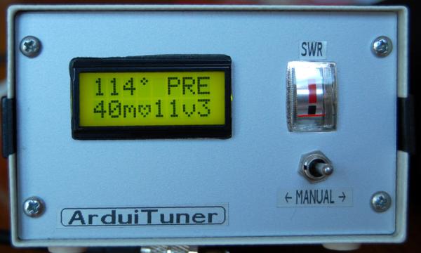
In practice, this complete procedure takes less than 10 seconds to complete. If the antenna is tuned in the middle of the band, there is no need to retune towards the edges, the matching is quite 'broad'. Once the best position is memorized (per band), the ATU automatically returns to this position when changing band - so there is no need to retune for each band change. If necessary, the position of the variable C can be fine-tuned manually in 1° steps (through a center position toggle switch).
-
-
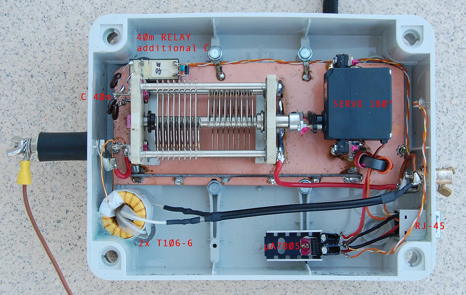
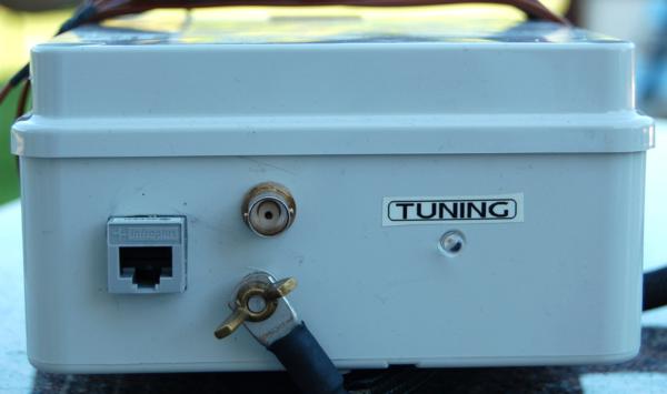
The ATU box is connected to the control bow by a standard CAT5 network cable and RJ-45, this is very handy. The signal handles supply (+12v) and control signal to servo, and power to the 40m band relay.
-
Servo Control : The servo I used seems to be quite sensitive to HF, it is true that very high RF voltages are present around the tuning box. Consequently, power is only applied to servo during tuning sequence (this happens at low power). ARDUINO switches +12v to ATU box, where the voltage is reduced to +5v by a µA7805 After tuning is completed, during normal transmissions at high power, the servo is not powered thus in 'deep sleep'...
-
IC-7000 interface and control : As the SWR can't be read by CAT commands during tune sequence initiated from the pushbutton on front panel, I decided to handle the complete tune sequence by ARDUINO and CAT commands. This works as follows :
-
A 'long' press on the tune button is detected as a 'request to tune'
-
This first initiates a sequence to retrieve by CAT the actual mode and power settings
-
The transceiver is then set to low power (2 .. 4 w RF) and RTTY mode, the dial is LOCKED
-
Then put in transmit mode (by CAT)
-
The tune sequence is initiated (servo searching for best SWR)
-
When the best tune position is found, the TRX is set back to RX and the original settings (power & mode) restored, the dial is UNLOCKED
-
The advantage of above method is that the power during TUNE can be freely adjusted by the sketch setup parameters. This can be required because at high power (in my case > 5w RF), there were errors with servo (becoming instable) and/or data errors on the CAT line (Transceiver not returning to RX mode after TUNE/TX sequence) Other possibility is to use the built-in TUNE feature of rig, but it then might be required to adjust the TUNE power in IC-7000 internal settings (accessing the service menu). Anyhow, the sketches for the 2 variants are provided (the one with built-in TUNE feature much less complex - but not my preference !).
-
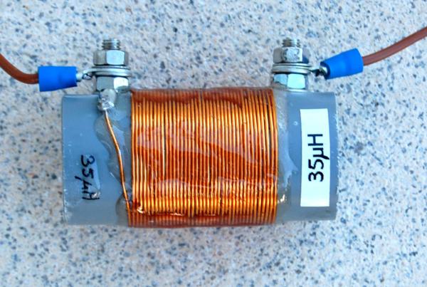
The antenna : is made from flexible PVC wire section 0.75mm². First a length of 8m57 ('20m section'), then the 35µH coil, then a length of 1m63 ('40m section'). Attention : these lengths are quite critical ! I spent hours finding these by trial & error.... start with these values and feel free to further adjust according to your conditions. The coil of 35µH is made of 38T close wound on PVC tube 32mm OD of enameled copper wire dia 0,5 or 0,7mm. This coil is protected by a layer of 2 component epoxy glue.
-
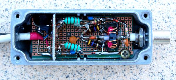
The SWR bridge: this is a standard SWR bridge, with diode forward voltage compensation - this allows SWR measurements with low power. See schematic here (pdf 110k) The reading to ARDUINO is relative only, this is fine to find a 'minimum', true SWR is not required. The reflected voltage is fed as well to a small angle analog meter, this is used as a check during transmissions and to adjust manually if required.
-
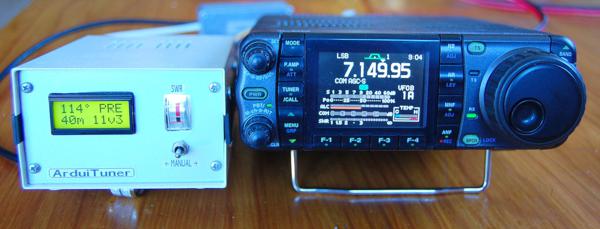
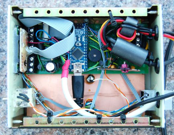
The control box: the control box houses an ARDUINO nano board and a LCD display 2x 8 characters with backlighting (see details here - pdf of 300kb) All wiring is RF-decoupled by ferrite chokes, ARDUINO runs fine under these conditions, but for security a 'heartbeat' signal is shown in the display. The LCD display shows the operating band, the set point / actual angle of the variable C, the relative SWR voltage, the power supply voltage, the status (TUNING, READY, ERROR, ....)
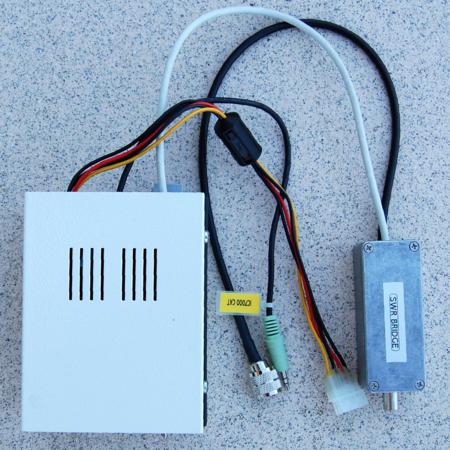
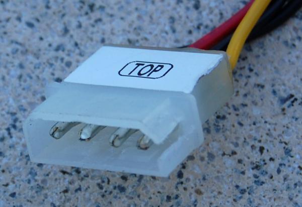
A minimum of cables / connections are required. The system is powered through the ATU connector of IC-7000. To emulate the original MOLEX, a plug was made out of a PC internal power plug, where on one end a section was cut out to match the mating plug on TRX.
Pins from L to R = 4 3 2 1
Pin 1 is the KEY pin, when the 'TUNE' button is pressed, it's pulled low by the tuner to tell the radio to start transmitting.
Pin 2 is the START pin to/from the microprocessor. Under normal circumstances the START pin is pulled high (to +12v via a 47k resistor) when a remote tuner is attached to tell the radio that the tuner is present. When you press 'TUNE' on the radio front panel, the radio pulls the pin low telling the tuner to start the matching sequence.
Pin 3 is POWER rated for 1 amp max and switches on and off with the radio. This powers the ATU.
Pin 4 is ground.
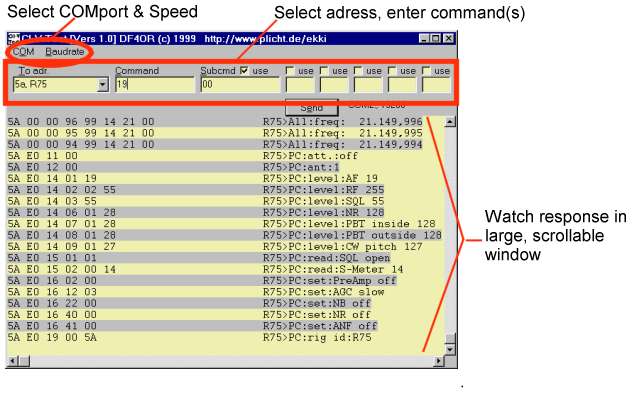
Recommended sites : have Google looking out for df4or.de - the site of Ekki is explaining Icom CAT up to bit and byte level ! He has written some nifty software to decode frames and analyze what is happening ...
Other inspiring information :
-
see PA3HCM Ernest's site http://ernest.utreg.net/?page=arduino-tuner
-
see WW3WW Alain de Carolis site : http://www.alain.it/2012/02/10/ft-817-automatic-loop/
Below are the sketches - in 2 variants or download version 1 (=by internal TUNE) or download version 2 (=fully by CAT) . It was compiled with IDE version 0022.- IMPORTANT : please use the same or you might get errors when compiling ! You still can download previous versions from ARDUINO website
A rough sketch of interconnections to ARDUINO, IC-7000, Tuner can be downloaded as PDF here !
(see other ARDUINO stuff under 'PROJECTS' page)
///////////////////////////////////////////////////////
//                                                   //
//     ATU FOR END FED HALF WAVE ANTENNA 20 & 40m    //
//                   by ON7EQ                        //
//                                                   //
//         using the rig internal TUNE feature       //
//                                                   //
///////////////////////////////////////////////////////


#include <Servo.h>     // We will use a servo
Servo servo;           // for rotating the capacitor

// include EEPROM write - required to memorize best antenna position
#include <EEPROM.h>

#include <NewSoftSerial.h>
// Use pins 2 and 3 to talk to the CAT. 2 is the RX pin, 3 is the TX pin
// Connect the RX pin to the CAT output through a 4k7 resistor.
NewSoftSerial CATserial =  NewSoftSerial(2, 3);

#include <LiquidCrystal.h>
// initialize the library with the numbers of the interface pins
LiquidCrystal lcd(7, 8, 9, 10, 11, 12);

//// DEFINE FIXED DATA /////

#define TrxAddress (102)           // 102 = HEX66 = IC746Pro / 7400
#define LowPowerSet (8)            // this DEC figures sets the low power output level (max = 55 !) 25 = 5w about 5 = 2w about
#define servoControlPin (4)        // attached to pin 4
#define servoPowerPin (A5)         // attached to pin A5: H = power to servo
#define backLash (9)               // servo backlash
#define TuneRequestPin (5)         // attached to pin 5 : L = Tune request by Transceiver
#define TuneTxPin (13)             // attached to pin 13 : L = setr TRX in Tune mode
#define BuzzerPin (A0)             // attached to Analog pin 0 : H = Buzzer beep
#define manualTunePin (A1)         // toggles switch attached to Analog pin : 0 = down, +5v = up; 2.5 v = idle
#define VccMeasurePin (A4)         // attached to Analog pin 4 : Voltage measure (1k2 to GND, 4k7 to Vcc - max 25v)
#define SwrFwdPin (A2)             // attached to Analog pin 2 : SWR Forward probe  (max 5v)
#define SwrReflPin (A3)            // attached to Analog pin 3 : SWR Reflected probe  (max 5v)
#define relayPin (6)               // attached to Digital pin 6 : Relay control - High = 40m select
#define R1           (12)          // from GND to VccMeasurePin, express in 100R  (12 = 1200 Ohm)
#define R2           (47)          // from + power supply to VccMeasurePin, express in 100R  (47 = 4700 Ohm)


/// SOME VARIABLES

int i;
int incoming;
int buffget[10] ;                             // the receive buffer

int Swr_fwd = 0;
int Swr_refl = 0;

unsigned int SupplyVoltage = (0); // Power supply voltage

byte capPos = 255;
byte bestCapPos = 0;
byte HighCapPos = 0;
byte LowCapPos = 0;

byte refl = 0;
byte bestRefl = 255;

byte ActMode = 0;                               // Actual mode
byte ActPwr_msb = 0;                            // Actual power msb
byte ActPwr_lsb = 0;                            // Actual power lsb

byte  TuneRequestPin_status = (1);              // High level is idle
long  TuneRequestPinbuttonTime = 0;
long  HeartBeatTime = 0;
long  lastCat = 0;

int unsigned long MHZ = 0;
int unsigned long KHZ = 0;
int unsigned long HZ = 0;
int unsigned long QRG = 0;
byte band = 0;                                  //actual band
byte oldband = 0;                               //previous band


// read commands
byte swr_read[7] = {254,254,TrxAddress,224,21,18,253};           // SWR read command
byte read_trx_id[6] = {254,254,TrxAddress,224,25,253};           // read TRX ID, irrespective if actal address
byte mode_read[6] = {254,254,TrxAddress,224,04,253};             // read mode: response $FE $FE $EO ra $04 $03 $02 $FD // $03 = CW
byte rf_power_read[7] = {254,254,TrxAddress,224,20,10,253};      // read RF powermode: response $FE $FE ra $E0 $14 $10 $yy $yy $FD
byte qrg_read[6] = {254,254,TrxAddress,224,03,253};              // read frequency


//write commands
byte dial_lock[8] = {254,254,TrxAddress,224,22,80,01,253};       // dial lock
byte dial_unlock[8] = {254,254,TrxAddress,224,22,80,00,253};     // dial unlock
byte low_power[9] = {254,254,TrxAddress,224,20,10,00,LowPowerSet,253};    // low power
byte tx[8] = {254,254,TrxAddress,224,28,00,01,253};             //turn Tx on
byte rx[8] = {254,254,TrxAddress,224,28,00,00,253};             // goto receive

byte mode_fm[7] = {254,254,TrxAddress,224,6,5,253};              // FM mode
byte mode_rtty[7] = {254,254,TrxAddress,224,6,4,253};            // RTTY mode

byte mode_return[5] = {254,254,TrxAddress,224,6};                // 1st 5 bytes, need to be completed
byte rf_power_set[6] = {254,254,TrxAddress,224,20,10};           // 1st 6 bytes, need to be completed with $yy $yy $FD

byte degree [8] = {  // special character  'heartbeat' indicator
  B00100,
  B01010,
  B00100,
  B00000,
  B00000,
  B00000,
  B00000,
};
byte heart [8] = {  // special character
  B00000,
  B00000,
  B11011,
  B10101,
  B10001,
  B01010,
  B00100,

};

//////////////////////////////////////////////////////////////////////////////
////////////////////////////////   S E T U P  ////////////////////////////////
//////////////////////////////////////////////////////////////////////////////

void setup() {


  CATserial.begin(9600);

// set up the LCD's number of columns and rows:

  lcd.begin(8, 2);
  lcd.clear();


// Print a message to the LCD.

lcd.print(" ON7EQ");
lcd.setCursor(0, 1);
lcd.print("Icom ATU");

 pinMode(BuzzerPin, OUTPUT);
 digitalWrite(BuzzerPin, HIGH);
       delay(50);
 digitalWrite(BuzzerPin, LOW);

delay (2000);
lcd.clear();

lcd.print("Ver 1.08");
lcd.setCursor(0, 1);
lcd.print("03/2012 ");

delay (3000);
lcd.clear();

// create special characters

lcd.createChar(0, degree);
lcd.createChar(1, heart);


pinMode(TuneRequestPin, INPUT);

pinMode(servoPowerPin, OUTPUT);
digitalWrite(servoPowerPin, LOW);

digitalWrite(TuneTxPin, LOW);
pinMode(TuneTxPin, OUTPUT);

pinMode(relayPin, OUTPUT);

readFrequency();

TuneRequestPinbuttonTime = millis();

}

/////////////////////////////////////////////////////////////////////
///////////////////////////  L   O   O  P  //////////////////////////
/////////////////////////////////////////////////////////////////////

void loop() {


  waitbutton:

      if ((analogRead(manualTunePin) < 340) and (band != 0)) manualDown(); // manual tuning requested
      if ((analogRead(manualTunePin) > 680) and (band != 0)) manualUp();

      readFrequency();

      TuneRequestPin_status = digitalRead(TuneRequestPin);
      if (TuneRequestPin_status == 1) {
      TuneRequestPinbuttonTime = millis();  // reset  timer
      goto waitbutton;
       }
  if ((millis() - TuneRequestPinbuttonTime) < 50)  goto waitbutton;

// button is pushed !

   TuneRequestPin_status = 1;                  //Reset button
   if (band == 0) {                            // Band error !
        digitalWrite(BuzzerPin, HIGH);
                delay(30);
        digitalWrite(BuzzerPin, LOW);
                delay(60);
        digitalWrite(BuzzerPin, HIGH);
                delay(30);
        digitalWrite(BuzzerPin, LOW);
                delay(60);
        digitalWrite(BuzzerPin, HIGH);
                delay(30);
        digitalWrite(BuzzerPin, LOW);
                delay(60);
        digitalWrite(BuzzerPin, HIGH);
                delay(30);
        digitalWrite(BuzzerPin, LOW);

    delay(500);
    goto waitbutton;
    }

   lcd.setCursor(0, 1);
   lcd.print("-TUNING-");

    delay(100);                    // wait till tune button released / DO NOT REMOVE LINE !

enterTuneMode();

  servo.attach(servoControlPin,575,2650);

  bestCapPos = 0;
  bestRefl = 1023;
  digitalWrite(servoPowerPin, HIGH);
  delay(200);
  capPos = 0;
  servo.write(0);                 // turn capacitor to start position
  delay(600);                     // this will take a bit of time, so wait

  ///// find best reflection routine /////

  /// coarse

  for(capPos = 0; capPos < 181; capPos += 10) {   //every 10°

 // Check if not stuck

   if ((millis() - TuneRequestPinbuttonTime) > 30000) tuneError();

      servo.write(capPos);
      lcd.setCursor(0, 0);
      if (capPos < 100)  lcd.print("0");
      if (capPos < 10)  lcd.print("0");
      lcd.print(capPos, DEC);
      lcd.write(0);


//lcd.setCursor(0, 0);

      delay(150);   // Wait for servo


     Swr_refl = analogRead(SwrReflPin);
//   Swr_fwd = analogRead(SwrFwdPin);

   refl = Swr_refl;
   if (refl > 999) refl = 999;

 // end SWR by probe input

    lcd.print(" ");
    if (refl < 100)  lcd.print("0");
    if (refl < 10)  lcd.print("0");
    lcd.print(refl, DEC);

    delay (20);
    if (refl < bestRefl) {
      bestRefl = refl;
      bestCapPos = capPos;
      }
  }


 /// fine, every 1°

   HighCapPos = bestCapPos + 20;
   if (HighCapPos > 180) HighCapPos = 179;
   LowCapPos = bestCapPos - 20;
   if ((LowCapPos > 180) or (LowCapPos < 1)) LowCapPos = 0;
   bestRefl = 1023;
  servo.write(LowCapPos);           // turn capacitor to start position
  delay(400);                       // this will take a bit of time, so wait

  for(capPos = LowCapPos; capPos < (HighCapPos + 1); capPos += 1) {

  // Check if not stuck

   if ((millis() - TuneRequestPinbuttonTime) > 30000) tuneError();


      servo.write(capPos);
      lcd.setCursor(0, 0);
      if (capPos < 100)  lcd.print("0");
      if (capPos < 10)  lcd.print("0");
      lcd.print(capPos, DEC);
      lcd.write(0);


//lcd.setCursor(0, 0);

      delay(200);   // Wait for servo & vswr_refl voltage decay

     Swr_refl = analogRead(SwrReflPin);
//   Swr_fwd = analogRead(SwrFwdPin);

   refl = Swr_refl;
   if (refl > 999) refl = 999;

 // end SWR by probe input

    lcd.print(" ");
    if (refl < 100)  lcd.print("0");
    if (refl < 10)  lcd.print("0");
    lcd.print(refl, DEC);

    delay (50);
    if (refl < bestRefl) {
      bestRefl = refl;
      bestCapPos = capPos;
      // if (refl > bestRefl) goto endTuneProcess ;
      }
  }

  // select best capacitance

  lcd.setCursor(0, 0);
  if (bestCapPos < 100)  lcd.print("0");
  if (bestCapPos < 10)  lcd.print("0");
  lcd.print(bestCapPos, DEC);
  lcd.write(0);


  lcd.print(" ");
  if (bestRefl < 100)  lcd.print("0");
  if (bestRefl < 10)  lcd.print("0");
  lcd.print(bestRefl, DEC);


 endTuneProcess:

 capPos = capPos --;
 servo.write(capPos);
     delay (100);
 if (capPos > (bestCapPos - backLash)) goto endTuneProcess;


// Memorize best position

if (band == 20)  EEPROM.write(20,bestCapPos);
if (band == 40)  EEPROM.write(40,bestCapPos);


      lcd.setCursor(0, 0);
      if (bestCapPos < 100)  lcd.print("0");
      if (bestCapPos < 10)  lcd.print("0");
      lcd.print(bestCapPos, DEC);
      lcd.write(0);


       lcd.print(" ");
      if (bestRefl < 100)  lcd.print("0");
      if (bestRefl < 10)  lcd.print("0");
      lcd.print(bestRefl, DEC);

  // end tuning process

    lcd.setCursor(0, 1);
     lcd.print(" READY!  ");
    delay(200);
    servo.detach();
    digitalWrite(servoPowerPin, LOW);

    digitalWrite(BuzzerPin, HIGH);
    delay(100);
    digitalWrite(BuzzerPin, LOW);
    delay(100);
    digitalWrite(BuzzerPin, HIGH);
    delay(300);
    digitalWrite(BuzzerPin, LOW);
    delay(100);
    digitalWrite(BuzzerPin, HIGH);
    delay(100);
    digitalWrite(BuzzerPin, LOW);

exitTuneMode();

  }

/////////////////////////////////////////////////////////////////////////////////////////////////////////

void enterTuneMode() {

  delay(50);

  digitalWrite(TuneTxPin, HIGH);   // enter tune mode
   }

/////////////////////////////////////////////////////////////////////////////////////////////////////////

void exitTuneMode() {

  delay(500); // time to read SWR
  digitalWrite(TuneTxPin, LOW);   // exit tune mode
  delay(50);
 }

/////////////////////////////////////////////////////////////////////////////////////////////////////////

void readFrequency() {

   while (CATserial.available() > 0) CATserial.read(); // clear buffer
   delay (20);


 new_try:
    lastCat = millis();
    for( i=0; i<6; i++){          // send qrg read
    CATserial.print(qrg_read[i],BYTE); }
    delay(50);


  qrg_next:

  if ((millis() - lastCat) > 300)  goto new_try;

  if (CATserial.available() > 0) {
    lastCat = millis();
    incoming = CATserial.read();
    if (incoming == 254) {           // 1st byte is  an FE look for an FE to start
      goto qrg_start;
    }
     goto qrg_next;
  }

qrg_start:

  buffget[0] = 0;

  // delay(1);
  for ( i=0;i<10;i++) {                // get next 10 bytes
    if(CATserial.available() > 0) {
      buffget[i]=CATserial.read();     // load buffget with next 10 characters
      delay(2);                        //delay 1 ms if true, time for buffer fill
    }
  }


delay (10);                                     // delay is required to process buffer, do not remove !

  if (buffget[0] == 254) {                      // again FE , as 2nd character ?

    goto qrg_next1;
  }                                             // yes, now do '00' test
  goto qrg_next;                                // wrong array, get another


qrg_next1:

  if ((buffget[3] == 0) or (buffget[3] == 3) or  (buffget[3] == 5)     ){  // check to see if 4th char is 00 or 03 or 05 (=frequency)
    goto qrg_next2;
  }                                               // detected, goto next2

  goto qrg_next;                                  // wrong array, get another


qrg_next2:

// Check for last byte

  if(buffget[9] == 253 ){                       // look for FD at end of array
    goto frequency;
  }                                             // if FD detected, goto frequency
  goto qrg_next;                                // wrong command


frequency:                                      // we have frequency array on hand

    MHZ = (buffget[7]);

    MHZ = MHZ - (((MHZ/16) * 6));               // Transform bytes ICOM CAT
    if (MHZ >= 100)  goto qrg_next;             // wrong byte

    KHZ = buffget[6];
    KHZ = KHZ - (((KHZ/16) * 6));               // Transform bytes ICOM CAT
    if (KHZ >= 100)  goto qrg_next;             // wrong byte

    HZ = buffget[5];
    HZ = HZ - (((HZ/16) * 6));                  // Transform bytes ICOM CAT
    if (HZ >= 100)  goto qrg_next;              // wrong byte

  QRG = ((MHZ * 10000) + (KHZ * 100) + (HZ * 1)); // QRG variable stores frequency in MMkkkH  format

  band  = 0 ;                                   // Reset band info
  if ((QRG > 139000) and (QRG < 145000)) {
              if (oldband == 40) {              // band change detect
              servo.attach(servoControlPin,575,2650);
              delay(20);
              digitalWrite(servoPowerPin, HIGH);
              delay(100);
              capPos = EEPROM.read(20);
              lcd.setCursor(0, 0);
              if (capPos < 100)  lcd.print("0");
              if (capPos < 10)  lcd.print("0");
              lcd.print(capPos, DEC);
              lcd.write(0);
              lcd.print(" PRE");
              servo.write(capPos);
              delay(500);
              servo.detach();
              digitalWrite(servoPowerPin, LOW);
               }
       band = 20;
       oldband = band;
       digitalWrite(relayPin, LOW);
     }
  if ((QRG > 69900) and (QRG < 72100)) {
              if (oldband == 20) {            // band change detect
              servo.attach(servoControlPin,575,2650);
              delay(20);
              digitalWrite(servoPowerPin, HIGH);
              delay(100);
              capPos = EEPROM.read(40);
              lcd.setCursor(0, 0);
              if (capPos < 100)  lcd.print("0");
              if (capPos < 10)  lcd.print("0");
              lcd.print(capPos, DEC);
              lcd.write(0);
              lcd.print(" PRE");
              servo.write(capPos);
              delay(500);
              servo.detach();
              digitalWrite(servoPowerPin, LOW);
               }

       band = 40;
       oldband = band;
       digitalWrite(relayPin, HIGH);
     }

     lcd.setCursor(0, 1);
     if ((band == 20) or (band == 40)) {
     lcd.print(band,DEC);
     lcd.print("m ");
     }
     if (band == 0) {
       lcd.print("ERR ");
       lcd.setCursor(5, 0);
       lcd.print("---");
       }
  SupplyVoltage = analogRead(VccMeasurePin);        // Read power supply voltage
  SupplyVoltage = map(SupplyVoltage, 0,1023,0,(50*(R2+R1)/R1));
              if (SupplyVoltage < 100) {
                 lcd.print(" ");
                      }
                 if (SupplyVoltage < 10) {
                      lcd.print(" ");
                      }
                 lcd.print((SupplyVoltage/10), DEC);
                     lcd.print("v");
                 lcd.print((SupplyVoltage)%10, DEC);
   // Heartbeat
        lcd.setCursor(3, 1);
    if ((millis() - HeartBeatTime) < 1000) lcd.print(" ");
    if ((millis() - HeartBeatTime) > 1000) lcd.write(1);
    if ((millis() - HeartBeatTime) > 2000) HeartBeatTime = millis();
    }

///////////////////   M A N U A L   T U N E /////////////////////

void manualUp() {

   lcd.setCursor(0, 1);
   lcd.print("+MANUAL+");

  servo.attach(servoControlPin,575,2650);
  if (capPos < 180) digitalWrite(servoPowerPin, HIGH);
  delay(200);
  if (capPos  == 255) {
      digitalWrite(servoPowerPin, HIGH);
      capPos = 0;
      servo.write(0);      // turn capacitor to start position if cappos never updated
      delay(800);          // this will take a bit of time, so wait
      }

  digitalWrite(TuneTxPin, HIGH);

  againPlus:

  capPos = capPos ++;
  if (capPos == 181) {
      capPos = 180;
        digitalWrite(BuzzerPin, HIGH);
                delay(30);
        digitalWrite(BuzzerPin, LOW);
                delay(60);
        digitalWrite(BuzzerPin, HIGH);
                delay(30);
        digitalWrite(BuzzerPin, LOW);
      goto endPlus;
      }

  servo.write(capPos);

  lcd.setCursor(0, 0);
  if (capPos < 100)  lcd.print("0");
  if (capPos < 10)  lcd.print("0");
  lcd.print(capPos, DEC);
  lcd.write(0);

  Swr_refl = analogRead(SwrReflPin);
  refl = Swr_refl;
  if (refl > 999) refl = 999;
  lcd.print(" ");
  if (refl < 100)  lcd.print("0");
  if (refl < 10)  lcd.print("0");
  lcd.print(refl, DEC);

  delay(100);   // loop time high swr
  if (refl < 10) delay (100);  // running slow on low swr

  if (analogRead(manualTunePin) > 680) goto againPlus;
  if (analogRead(manualTunePin) < 340) manualDown();

  endPlus:
  delay(1000);
  if (analogRead(manualTunePin) < 340) manualDown();
  digitalWrite(TuneTxPin, LOW);

  lcd.setCursor(0, 1);
  lcd.print("  STOP  ");

  servo.detach();
  digitalWrite(servoPowerPin, LOW);
  delay(500);

  // memorize best position
  if ((capPos != 0) and (capPos != 180)){
        if (band == 20)  EEPROM.write(20,capPos);
        if (band == 40)  EEPROM.write(40,capPos);
       }

 }

 void manualDown() {

   lcd.setCursor(0, 1);
   lcd.print("-MANUAL-");

  servo.attach(servoControlPin,575,2650);
  if (capPos > 0)digitalWrite(servoPowerPin, HIGH);
  delay(200);
  if (capPos  == 255) {
      capPos = 0;
      servo.write(0);      // turn capacitor to start position if cappos never updated
      delay(800);          // this will take a bit of time, so wait
      }
  digitalWrite(TuneTxPin, HIGH);


  againDown:

  if (capPos > 0)capPos = capPos --;

  lcd.setCursor(0, 0);
  if (capPos < 100)  lcd.print("0");
  if (capPos < 10)  lcd.print("0");
  lcd.print(capPos, DEC);
  lcd.write(0);

  Swr_refl = analogRead(SwrReflPin);
  refl = Swr_refl;
  if (refl > 999) refl = 999;
  lcd.print(" ");
  if (refl < 100)  lcd.print("0");
  if (refl < 10)  lcd.print("0");
  lcd.print(refl, DEC);

  if (capPos == 0){
        digitalWrite(BuzzerPin, HIGH);
                delay(30);
        digitalWrite(BuzzerPin, LOW);
                delay(60);
        digitalWrite(BuzzerPin, HIGH);
                delay(30);
        digitalWrite(BuzzerPin, LOW);
        goto endDown;
        }

  servo.write(capPos);

  delay(100);           // loop time high swr
  if (refl < 10) delay (100);  // running slow on low swr

  if (analogRead(manualTunePin) < 340) goto againDown;
  if (analogRead(manualTunePin) > 680) manualUp();

  endDown:

  delay(1000);         // wait to show swr
  if (analogRead(manualTunePin) > 680) manualUp();

  digitalWrite(TuneTxPin, LOW);

  lcd.setCursor(0, 1);
  lcd.print("  STOP  ");

  servo.detach();
  digitalWrite(servoPowerPin, LOW);

   // memorize best position

  if ((capPos != 0) and (capPos != 180)){
        if (band == 20)  EEPROM.write(20,capPos);
        if (band == 40)  EEPROM.write(40,capPos);
       }

   delay(500);
 }

/////    TUNER STUCK / TIMEOUT  //////

 void tuneError() {

   lcd.setCursor(0, 1);
   lcd.print("-ERROR!-");

  servo.detach();

  digitalWrite(TuneTxPin, LOW);

        digitalWrite(BuzzerPin, HIGH);
                delay(60);
        digitalWrite(BuzzerPin, LOW);
                delay(100);
        digitalWrite(BuzzerPin, HIGH);
                delay(60);
        digitalWrite(BuzzerPin, LOW);
                delay(100);
        digitalWrite(BuzzerPin, HIGH);
                delay(60);
        digitalWrite(BuzzerPin, LOW);
               delay(100);
        digitalWrite(BuzzerPin, HIGH);
                delay(60);
        digitalWrite(BuzzerPin, LOW);

   delay(500);

   loop();
 }