Figure 2 - Input selection menu
If a Wav file is not open, the default behavior is to read from the sound card. The ”Input Mixer” choice is used to open the Windows mixer Recording Panel
Figure 3 - The Windows mixer panel
In Figure 3 the controls refer to a specific audio card. You may find some minor differences depending on the card you have on your PC. Just a note here : some semi-professional sound cards, notably the Delta 44 from M-Audio,do not implement in their drivers the functionalities needed for this panel. If you select “Input Mixer” when such a card is selected as input, you will receive an error message from Windows. If you use a Delta 44 sound card, please set its Control Panel as follows, where the important settings are the DMA Buffer Size, the Multi Track Driver Devices and the Rate Locked:
Figure 4 - How to set the Delta 44 Control Panel. NOTE:- The "Con" setting for the inputs is the best to match Softrock-type SDRs. The "Monitor Mixer" is not selected in Patchbay/Router.
On the right, the later version of the Control Panel all settings are available but in a different place.
Other choices present in that menu are the selection whether to use the WMME drivers for your sound card or the ASIO drivers (if installed).
Also in the Options
Colour Palette select type and the FFT_Windowing, window type. This latter choice does not refer to the Windows version, but rather controls which kind of windowing is done to the signal in the FFT process. If you don’t know what all of this means, leave the default set by the installation program (sin^5), which is the optimum for almost all the cases. There are no performance penalties in the choice of a window over another, as they are all precomputed.
The “Swap I and Q channels” choice is useful for hardware that outputs the I signal on the right channel and the Q signal on the left.
The “Channel Skew Calibration” choice activates a routine that allows to compensate for unbalances in the two channels of the sound card. More information is shown on the panel that opens when selecting that choice.
Pressing the “Select Sound Card” button you can choose which card to use, if you have more than one. Figure 5 is what I see on my PC.
Figure 5 - The sound card selection panel
Then you have the possibility to specify whether you want the volume “locked”. Right click "Volume" or in Options - Misc Options. What does this mean? When the volume is set to a too high level such as to cause saturation in the output sound card DAC, then the setting of the volume slider is lowered automatically. This is not always desirable, e.g. when there are strong atmospheric crashes caused by a nearby thunderstorm. You would end up with a too low volume level. In such cases it is useful to “lock” the volume slider, which means that the automatic adjustment is not performed. Of course you are still free to adjust it manually.
A further choice in MIsc Options is that of the Process Priority of Winrad. There is no a firm rule for this. Try both settings if you are experiencing audio dropouts, to see which one works better for your setup.
Another thing you have to select before starting is the sampling rate to use, and this can be done with the “Select Sample Rate” button, as shown in the following picture.
Figure 6 - Selection of the sample rate
When using the ASIO drivers, for some rates you may receive an error message stating that the current ASIO driver does not support that rate. It happened to me with the old driver for the Delta 44 card. The latest driver seems to have expanded the range of the supported rates. The output sampling rate is automatically chosen by the program to be 11.025 kHz, unless the Rx Mode is set to DRM or FM, in which cases the output sampling rate is 24 kHz, to be able to provide 12 kHz of audio band to the chained DRM decoder.
When you press the Start button, the program starts to acquire audio data, processes them and sends them to the DAC of the audio card. The upper window is divided into two panes, the waterfall and the spectrum. It is possible to choose how to assign the available space between the two panes by using the right mouse button. Just place the mouse pointer on the frequency scale. The pointer will change shape, indicating that you can drag left and right the portion of the spectrum that is displayed (keeping the left button down) or you can drag up and down (keeping the right button down) the frequency scale which divides the spectrum from the waterfall. Much more complicated to explain than to do…
Figure 7 - Two different ways to divide the space available in the upper window
Note that the effect of the drag (horizontally or vertically) will be apparent only when Winrad is started, i.e. when the waterfall is flowing. Similarly two sliders appear at both sides of the upper window only when the program is started. The left one controls the gain level and the right one the base level of the spectrum display, much as you would find on a hardware spectrum analyzer.
Ok, now the program is running, and you have to choose the decoding mode. Some purists will object to the use of the word “decoding”, as SSB signals are not encoded in any way, they are just translated in the spectrum. But please let me use this word to signify the process to bring them back to baseband. You choose the mode simply pressing one of the three buttons :
Figure 8 - Choosing the decoding mode
The DRM mode just widens the output bandwidth to 12 kHz, but does not do any decoding. You will need an additional software decoder, chained through a second audio card or the VAC (Virtual Audio Cable). No matter what your choice is, you will see in the upper window a light blue area, which corresponds to the limits of the passband currently set, and shown graphically on the lower window.
Note that the ECSS mode has three submodes chosen by repeated clicks on the ECSS button. By clicking on it, you will cycle through “Both sidebands”, “Left sidebands only” and “Right sideband only”. This is much useful when only one side of the AM station is interfered. By excluding that side the interference is eliminated. The blue window on the upper waterfall will reflect the submode currently chosen.
Figure 9 - How the passband (filter width and slope) is shown in both windows
Note that the shape in the lower window is not an approximation of the passband. It is the *real* passband, dynamically computed and graphed while the program is running. Even the ripples due to the Gibbs phenomenon are visible. As you can see in Figure 9, it has an out-of-band rejection of more than 160 dB, thanks to the 1537 taps equivalent FIR filter used for the computation of the fast convolution.
Changing the limits of the passband is quite easy. Just place the mouse cursor on the upper or lower limit, the cursor shape will change indicating that you can now drag that border, as shown in Figure 10.
Figure 10 - Dragging the upper passband limit with the mouse
To drag that border, simply press the left mouse button and move the mouse keeping the button pressed. Similarly for the lower border. You can do this operation only when the program is processing input, i.e. when the Start button has been pressed.
To tune the desired signal while in SSB mode, click in the upper window on the frequency of the (suppressed) carrier of the SSB signal. This frequency is shown with a gray line and reported numerically above the window. Alternatively, you can drag the light blue window itself, by placing the mouse cursor inside it. The cursor shape will change and dragging is now possible. Fine tuning is possible with the mouse wheel, in steps of 10Hz.
The upper and the lower frequency scales
Right Click "LO" or "Tune" to lock frequencies.
The upper scale indicates the frequency of the LO, Local Oscillator, centre frequency, which for soundcard SDRs is usually the actual LO.The lower "Tune" frequency represents the internal NCO (Numerically Controlled Oscillator) used to bring to zero IF the signal, summed to the frequency of the external LO. Hence, for SSB modes, it corresponds to the (suppressed) carrier frequency. For CW it corresponds to the CW signal frequency. The NCO frequency is the frequency of the internal software oscillator used to bring to baseband the received signals, and its value, as said above, is summed to the value of the external LO so that to indicate the tuned frequency in the display marked Tune :
Both those values can be changed using the mouse. If you hover the mouse on one digit of either displays, that digit is marked as being changeable. You can change it either by rotating the mouse wheel, or by keeping pressed the left mouse button (continuous auto increase) or the right mouse button (continuous auto decrease)
When Winrad is used with a companion DLL meant to control an external hardware, like the Softrock, SDR-14, SDR-IQ, Perseus or the SDR-X, changing the LO value with the mouse has the effect to change the frequency where the hardware is tuned to. When playing back WAV files recorded with the ‘rcvr’ tag (as those recorded with Perseus), the LO will be automatically set to the value it had at the time of the recording. You cannot change it during the playback.
The lower scale indicates the offset from the frequency indicated on the upper window, so for SSB it shows the audio frequencies of the signal received. The scale reversal when in LSB mode is automatically taken care of by the program. When in CW mode, the lower scale indicates the pitch of the CW note, which is user-settable. In CW mode a faint gray line appears in the center of the passband, in correspondence with the pitch set. When in this mode, the tuning can be refined by clicking on the lower window (spectrum or waterfall, doesn’t matter). The frequency clicked on will be made the new carrier frequency, and hence positioned under the gray line, in the center of the passband.
To change the desired CW pitch frequency (default 550 Hz), position the mouse cursor in the lower window on the desired pitch, then press the right mouse button, while keeping pressed the Ctrl key on the keyboard.
p11 Figure 11 The control buttons panel
Figure 12 - The adjustment of the denoiser level
Right Click NR Button.
Figure 13 The adjustment of the Noise Blanker Level
Filters
When needed, a few filters can be applied to the signal, to make the reception better. One of the audio filters that it is possible to insert when receiving is the Denoiser, or Noise Reduction Filter, that is activated with the NR button as shown in Fig. 11.
Its aggressiveness can be controlled by a slider that appears when right-clicking on that button. See Fig 12. This denoiser is especially effective in presence of the so-called AWGN (Additive White Gaussian Noise), in other words the common hiss.
Its effectiveness with impulsive noise is limited. For this type of noise the Noise Blanker filter is more indicated. A word of caution here. The Noise Blanker, if inserted in absence of impulsive noise, can make the reception worse… so use it only when needed, starting with its Strength set to the minimum, and slowly raising it up to the point where the reception becomes possible.
On one of my Web sites there is a wav file that you can download to test the working of the Noise Blanker.
Get it from http://sundry.i2phd.com/CQ_EME.wav
It is a large file, slightly more than 10MB. When processing it, set first the Mode to I/Q, the LO frequency on the upper window to zero, and the Tune frequency to -12343Hz, CW mode. Try both with and without the Noise Blanker. Insert also the Denoiser and the CW Peak filters. Without the filters, it will be impossible to copy the call sign of the caller. With the filters active it will become an armchair copy. The file has been produced using a similar file downloaded from the Flexradio Web site.
The CW Peak filter, just mentioned, is a combination of a dynamic expander and a peaking filter, and can be activated only when in CW mode. The peaking filter has the shape shown in Fig 14 below, simulated with Matlab.
Figure 14 - The shape of the CW Peak filter
It is implemented as a simple IIR resonator. You can control its “pointedness” with the slider that is shown when you right-click on the CW Peak button. It’s the digital equivalent of a Q-multiplier in the analog domain. Differently from the analog Q-multiplier it cannot be pushed into oscillation, as this is prevented by the software, but if you push it to the extreme, the peak will become so narrow to not leave the CW manipulation pass… dots and dashes will sound as a semi-continuous tone, the filter is ringing, as any IIR filter has the rights to do… To make the best use of this filter, pay attention tothe fact that the CW signal is centered in the passband in the lower window, in other word it is positioned on the gray line indicating the CW pitch. You can use the ZAP button (described below) to do this automatically.
The other controls
Figure 15 - The control buttons
In Fig. 15 at the left the Level meter indicates, in S-units, the strength of the signal, to which it is logarithmically related. The full scale corresponds to the saturation level of the sound card ADC. Right to it, the slider AGC Thresh. sets the knee of the AGC slope.Above this knee, the slope is kept almost horizontal, so to have a constant audio level. Below the knee, the slope is almost linear, in the sense that the differences in signal strength are no more compensated. Pay attention to the fact that the slider has a reverse behavior : when at its minimum, the knee is high, and viceversa. This has been done to make its use more intuitive. Try to use it when listening just at the weak background noise, and it will become clear.
The Vol slider is just a volume control. Its background will turn red when the level has been set too high, and there are audio peaks greater than the full scale value of the sound card DAC (which will be clipped).Right click to lock the volume.
AGC Fast/Slow/Off is selected by clicking the button. The attack time is fixed and quite fast. A short hang has been implemented, which goes almost unnoticed. The Mute button does just what its name implies, i.e. it mutes the audio output.
Referring to Fig 15, the CW ZAP button can be used only when in CW mode, and it searches for the strongest peak in the passband in the lower window, and adjust the NCO frequency so to center that peak, which will now be set at the CW pitch frequency. It doesn’t stick, it has a momentary action. When you want to use it again, you simply press it again. It can also be activated by pressing the key Z on the keyboard.
The AFC button, also active only in CW mode, tries to keep the signal peak centered in the passband, continuously adjusting the LO frequency. In this release of Winrad, the speed of this “frequency hunting” is fixed, but probably in one of the next releases it will be made adjustable.
Figure 16 - The waterfall Gain and Contrast controls
Both windows have two controls, Gain and Contrast, with which you can optimally set the mapping between the waterfall brightness and the intensity of the signal. If properly adjusted, the waterfall can show traces of signals so weak to be inaudible. If you know my other program Spectran, the behavior is similar.
Figure 17 - A few controls below the upper window
With the speed control you adjust the refreshing speed of the spectrum and the waterfall displays. The /10 button divides the current speed by ten, so to allow for very low refreshing rates. The button marked F (which means Full) unlocks the spectrum display speed from that of the waterfall. If activated, the spectrum display will run always at full speed, while the waterfall speed is set by the controls. The button marked Rev (Reverse) makes the waterfall flowing from bottom to top (never heard of water falling up instead than down, but some, myself included, prefer this behavior). And finally the button WF Avg applies the averaging not only to the spectrum, but also to the waterfall.
The two arrow buttons increase or decrease the resolution of the display. The Hz value indicated is the width of the FFT bin, which always corresponds to a single pixel. Making the resolution finer increases the CPU load, and makes worse the time resolution, so adjust it wisely.
Figure 18 - The controls under the lower window
Under the lower window there is the speed control, similar in function to that of the upper window, the left and right arrows to control the resolution, and a button marked F (which means Full band), that controls whether the spectrum displayed must be windowed by the passband limits or not. This buttons has effect only in CW mode. Look at the two different cases :
Figure 19 - The F button is *not* pressed
Figure 20 - The F button *is* pressed
Of course, the F button affects only the display, not the audio, which will always be affected by the passband limits set. The button WF Avg is similar in function to the similar button below the upper window, but now it relates to the lower window waterfall.
Figure 21 - Some other controls
Using the upper three buttons in Fig. 21 it is possible to tailor the spectrum and the waterfall displays in both windows so to give more importance to the frequency resolution or to the time resolution, or to compromise between them. Make your choice depending on the characteristics of the signal. For normal speed CW signals, you may certainly want to leave it set to Time.
The two bars at the bottom indicate the current CPU load, both that imputable to Winrad, and the overall load caused by the sum of all the programs running, Winrad included. This display is available only when Winrad runs under Windows 2003 or XP, but not Win98 nor Windows 2000.
The round indicator on the left measures the phase delta between the carrier of the AM signal being received and the internal NCO of the program, used to bring to zero IF that carrier. When in ECSS mode the outer ring can be either blue (meaning that a lock with the carrier has not been acquired) or green (meaning that we are in locked status). Counting the revolutions per second, an indication of the frequency difference can be obtained. E.g. one revolution per second means 1 Hz of frequency delta.
WAV files playback
Playback of WAV files is straightforward. Winrad can accept 8, 16, 24 or 32 bit files, either integer values (mode 1) or floats (mode 3). If the recording was made either with SpectraVue or with Perseus, Winrad is able to extract the LO information coded in the file header, and to set the LO display of the program to this value.
When playing back, the following controls appear
They are similar to the normal controls found on a VCR or a DVD player
You can reposition in real time the virtual tape by just clicking on the horizontal bar that indicates the progress of the playback :
WAV files recording
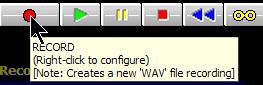
Note the Right Click for the configuration window.
Winrad can record into an IQ WAV file the wideband signal present at its input. The sampling rate will be set equal to that of the input signal, and the same will be for the number of bits. For example, if a recording is being made using Perseus, it will have 24-bit samples. Also when using the Delta 44 sound card with its ASIO drivers, the recorded samples will have 24 bits each. In more normal cases the samples will be of 16 bits each.
The WAV file will have an automatically generated filename, with a time stamp on it. The file header will also contain the LO frequency, which will then be set in the program display when playing back. The files are placed in the same directory where the Winrad executable resides.
Due to Windows and the WAV file header limitations, each WAV file is limited to a max length of 2GB. When this limit is reached, the file is closed, a new file is open and the recording continues seamlessly for the user. The files so generated are linked, so during the playback at the end of a file the next linked file is open and played back, without any disruption of continuity for the user.
Keyboard shortcuts Winrad is mainly driven by the mouse, but some action can be performed also using the keyboard,
Click Help/Update or press F1 for a list of keyboard shortcuts.
Note the links for Update.
Also look at all the pages on the HDSDR site. There is useful and interesting information there.
Included is a list of all SDRs that are supported by HDSDR.
Some caveats
Now a few words about the sound card sampling frequency, and the consequences of errors in its value. If this world were perfect, a sampling rate of 48 kHz would be exact, and so would be 8 kHz. If this were the reality, then I could produce one output buffer at 8 kHz out of 6 input buffers, and everything would work ok. Unfortunately this is not how things are... the sound card sampling rates have errors, and the consequence is that, if I downsample exactly by a factor of 6 going from 48 to 8 kHz, I would have either buffer starvation or buffer overflow depending on the real ratio being lower or greater than 6.
To remedy to this problem, the only solution is to monitor the number of buffers ready for output and to change dynamically the decimation ratio so to keep this number constant. This value is of course a discrete, integer, number, not a continuous variable, and this complicates a bit the computation of the optimal decimation ratio. That notwithstanding, when real sound cards are involved, the algorithm converges in an acceptable lapse of time, and then the decimation ratio becomes a rather stable number. With using e.g. the SDR14 hardware the input soundcard is replaced by the USB port, which is where the audio come from. Under Windows the USB port is not designed for a constant, steady flow of data, but rather as a block device, where large amount of data are pumped a chunk at a time, with some unavoidable jerkiness. This perturbs that computation, and the result is that the computed optimal value cycles around a mean value, and it is possible to observer this effect in the lower window. Here you see the frequency changing slightly, as a variation of the decimation ratio involves a different final frequency for the signal.
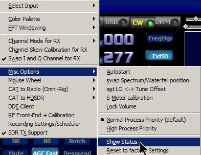
The value of the decimation ratio is shown in the Status panel, that can be opened by a choice in the Show Options menu.
Figure 22 - The Status panel
Winrad tries to keep the value of the output buffer queue length to 6, by adjusting the decimation ratio. The button marked “Lock” can be used to lock temporarily the current value of the ratio. This will stop the wandering of the output frequency, but of course it will eventually result either in the queue length value going to zero (causing clicks in the audio) or increasing up to the maximum allowed, causing some automatic discard of buffers to avoid overflow.
If you see that Winrad has problems in reaching a stable value for the decimation ratio, there are a couple possible remedies. One is to “Force” the output sampling rate to be equal to the input, using the same card both for input and output (if you use two different cards, there is no guarantees that the two rates are equal). The other is to use the ASIO drivers for the card, if they exist for that specific model of sound card. Using the ASIO drivers, the input and output interrupts on the card are coupled, so they are guaranteed to happen simultaneously, exactly at the same time.
Well, this more or less ends this synthetic User Guide, which I hope will make you able to use Winrad in an acceptable way. I would like to thank Jeffrey Pawlan WA6KBL, whose invaluable advice has been of great help during the development of the program, and thanks also to the beta testers who gave suggestions on how to improve Winrad. If you live in the US, and would like to have guidance on the use of Winrad from a person who speaks your own language, you may contact Jeffrey at [email protected]. If you are in an European Time Zone and prefer to contact me, my email address is [email protected]. Winrad is freely downloadable from http://www.weaksignals.com Enjoy the program and please give feedback, positive or negative, about its use by joining the Winrad Yahoo group, which you can do by sending a message to me, requesting an invitation for the membership. Thanks. Alberto I2PHD [email protected]
ASIO is a trademark and software of Steinberg Media Technologies GmbH


