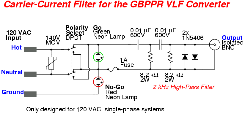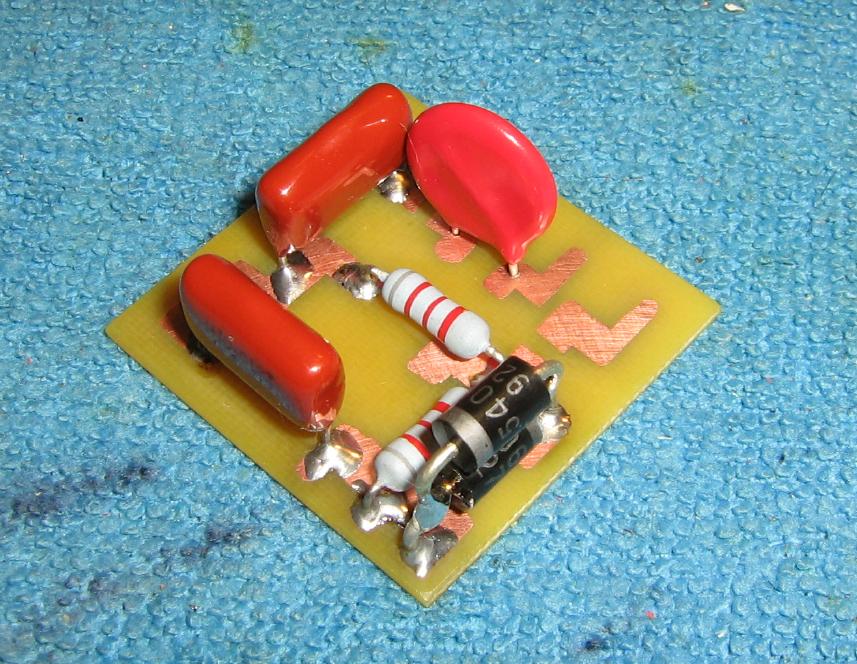
Overview of the passive 2,000 Hz high-pass filter circuit.
It consists of two 0.01 µF (600V, AC-rated) non-polarized Mylar capacitors, two 8.2 kohm (2 watt, flame-proof) resistors, two 1N5406 diodes, and a 140 volt MOV.
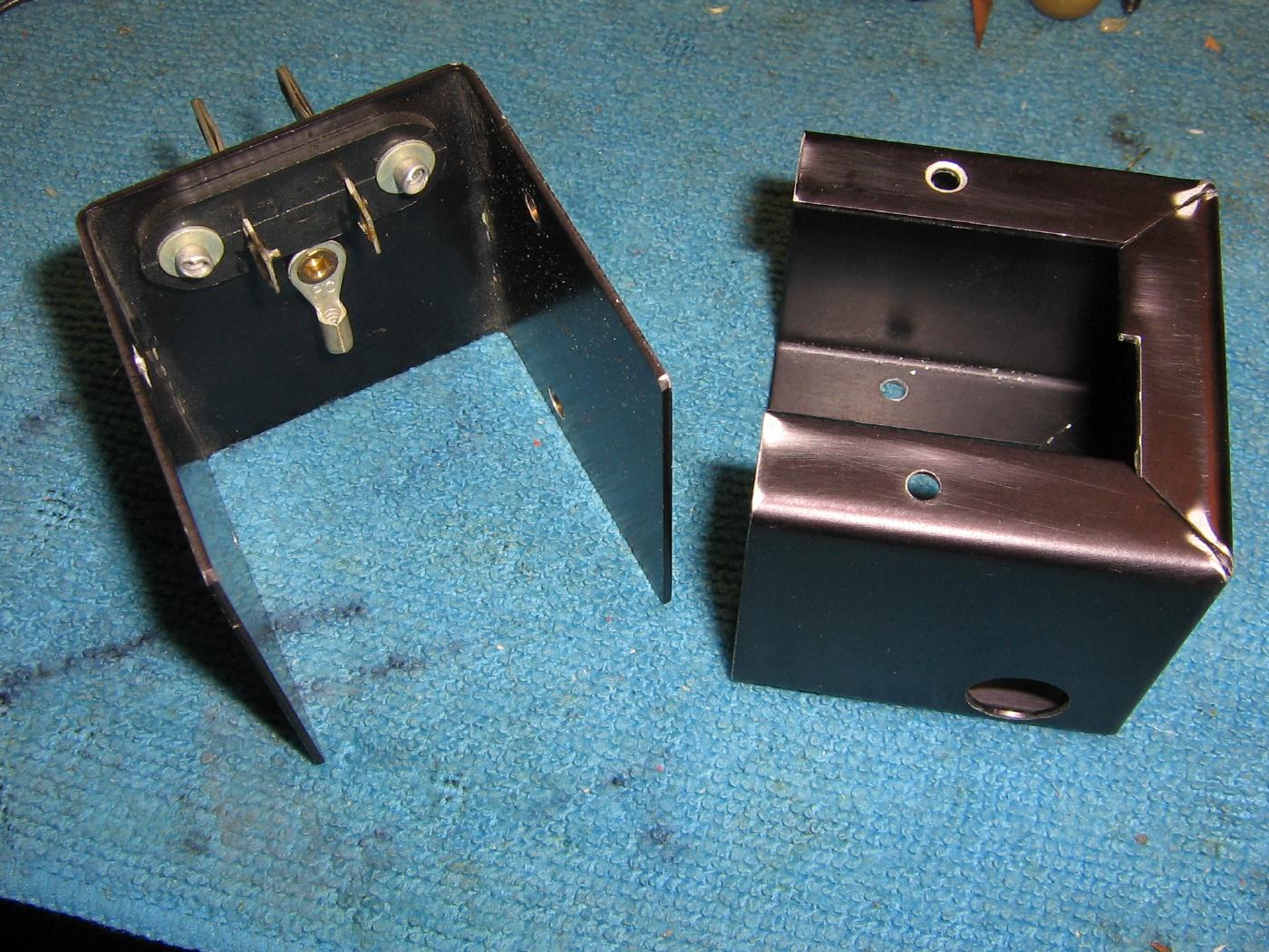
The high-pass filter circuit will be mounted inside an old metal "wall wart" power supply adapter I found at a ham radio swapfest.
These types of AC power adapters are often used for "industrial" equipment.
A large plastic AC power adapter will also work, provided it has access screws.
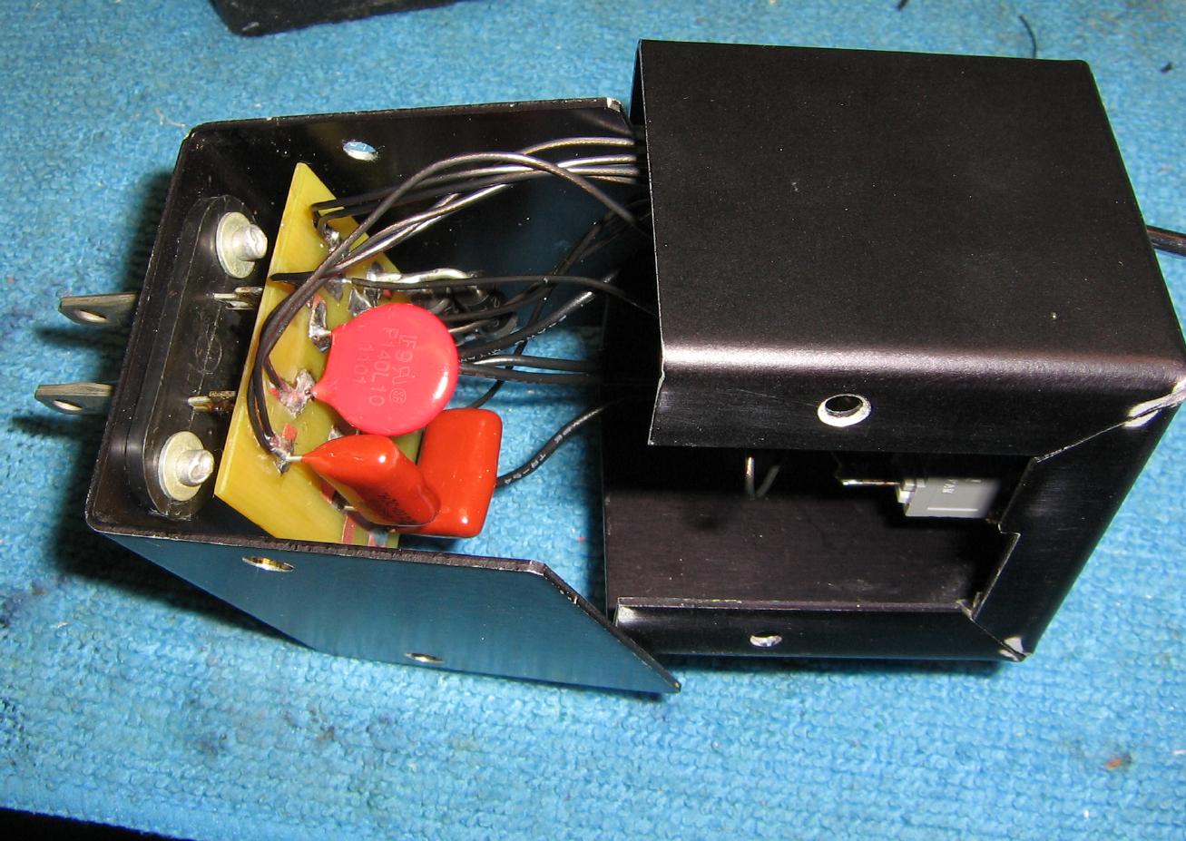
Mounting the circuit board inside the "wall wart" power supply adapter.
Try to use Teflon insulated wire to prevent shorting.
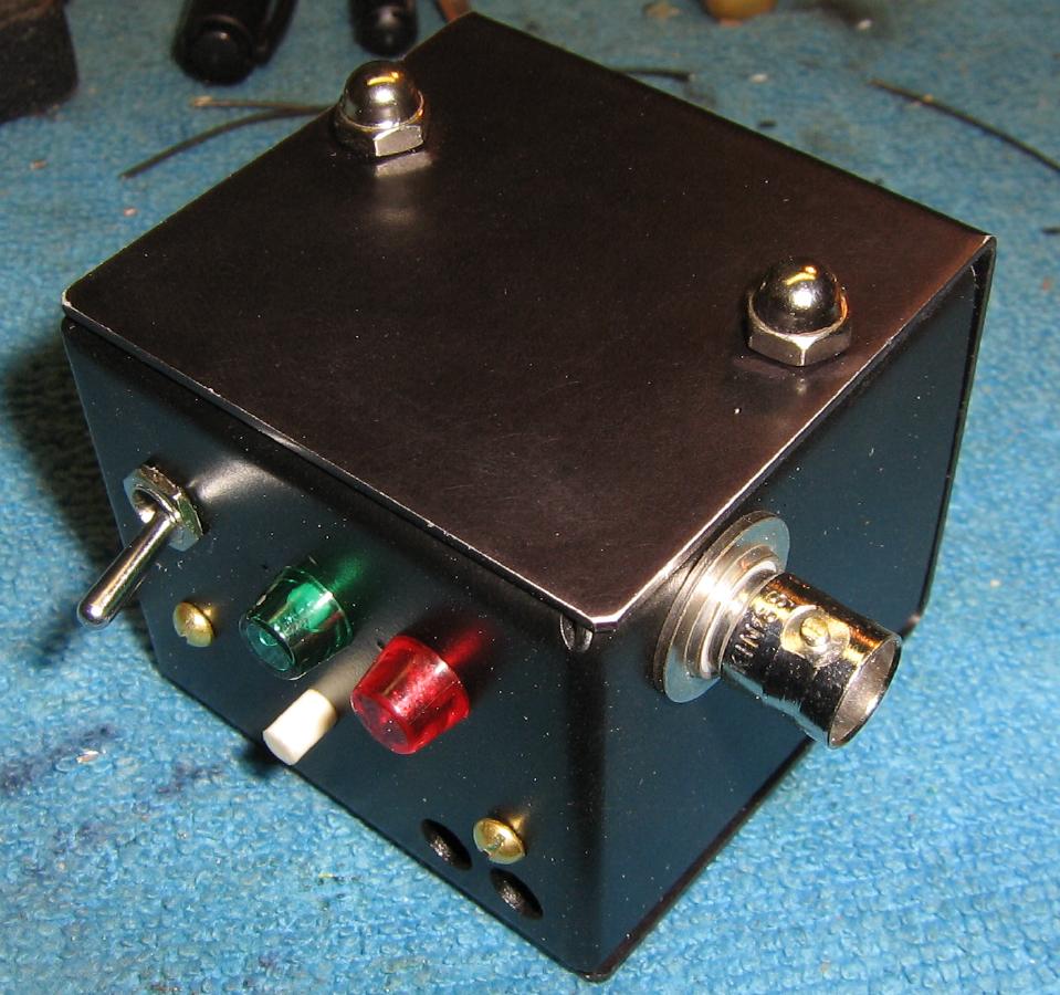
Overview of the completed filter.
The rear of the adapter will have the two Go/No-Go neon lamps, the Polarity Select switch, and the access probe for the resettable fuse.
The isolated BNC jack for the filtered output is mounted on the bottom.
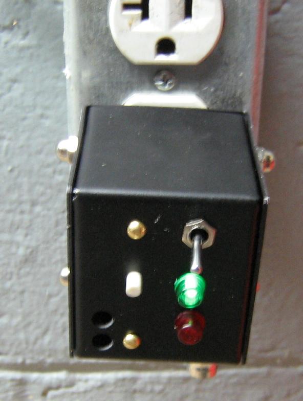
Testing the filter probe with an active 120 VAC power outlet.
If the GREEN lamp is lit, the polarity is correct. If the RED lamp is lit, flip with Polarity Select switch, which should light the GREEN lamp. If that doesn't work, quickly disconnect the filter and check the outlet manually with an accurate AC volt meter.
To perform a carrier-current TSCM sweep, check various outlets around the target location to see if there are any unknown signals. If you do happen to find something, keep moving the filter probe outlet-to-outlet until the signal is the strongest.
While monitoring the unknown signal, start unplugging the various devices plugged into the AC outlets until the signal drops. Carrier-current transmissions can't make it past transformers, so if you do find a signal, the source is probably physically close.