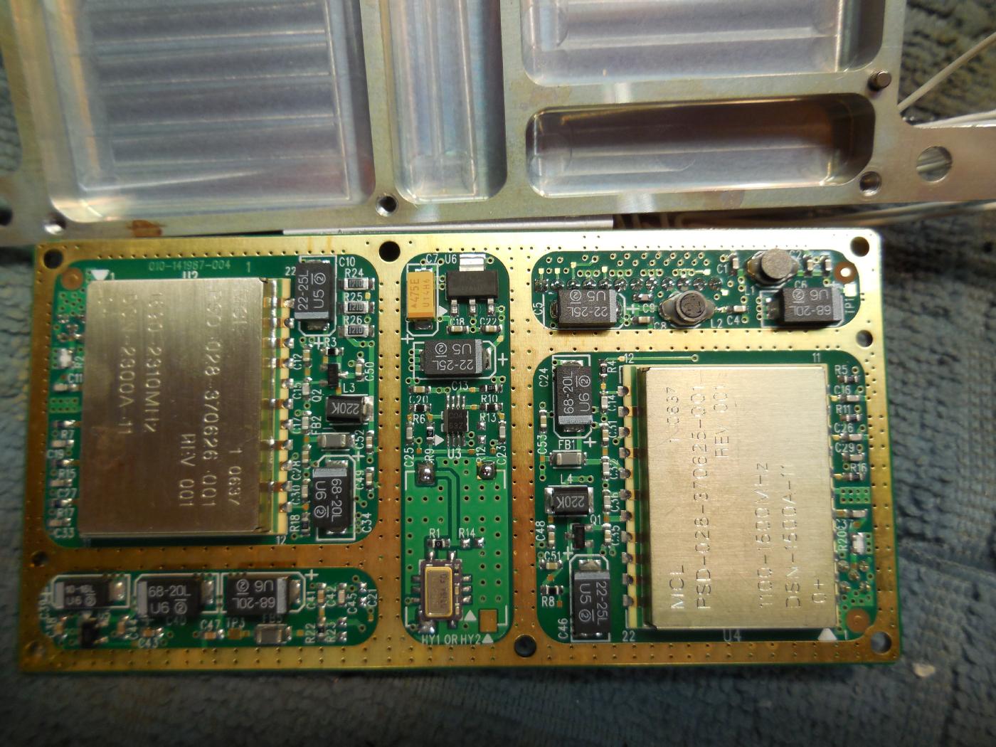
The Mini-Circuits DSN-2300A-1119+ frequency synthesizer used for this tracking generator is from an oscillator board I found on eBay. It has no markings other than "P/N: 131-141987-001 IF LO CARD."
It has two MMCX female connectors labeled "TX IF LO" and "RX IF LO."
This particular unit also has a Mini-Circuits DSN-1500A synthesizer for generating a signal between 1100-1500 MHz and an on-board 10 MHz clock oscillator.
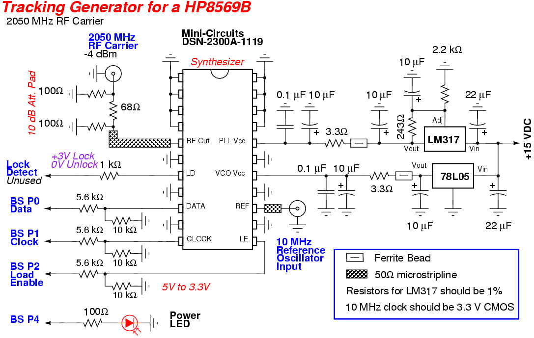
Only the Mini-Circuits DSN-2300A-1119+ frequency synthesizer and the 10 MHz reference clock oscillator (3.3V CMOS) are needed.
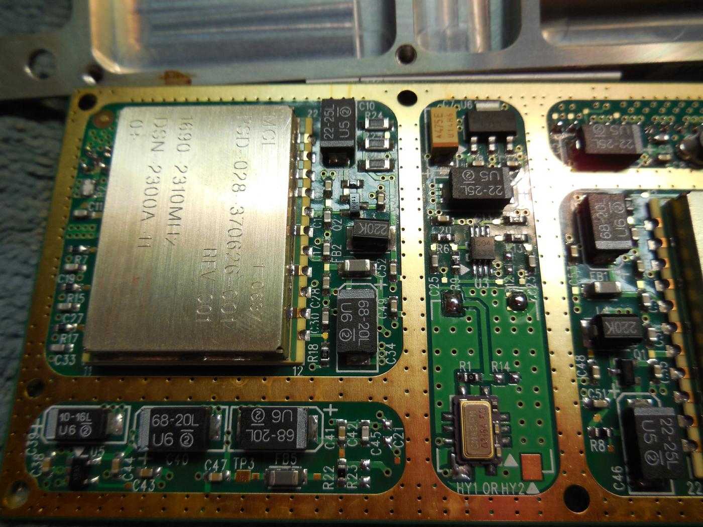
This oscillator board has its own 10 MHz reference clock oscillator, as shown on the lower-right.
Any standard 10 MHz 3.3 volt CMOS clock oscillator will work. Frequency stability is only required on the narrow resolution bandwidths.
It doesn't appear possible to tweak this reference oscillator frequency, but the output frequency was very stable. Slightly tweaking the 2050 MHz carrier frequency (+/- 100 kHz) is handy because the center frequency of the IF filters in the spectrum analyzer can drift over time and you may have to "peak" the response during narrow resolution filter sweeps.
The final output frequency was 2049.998253 MHz (-1747 Hz) at -4.3 dBm.
The DSN-2300A-1119+ puts out around +6 dBm and there is an on-board 10 dB attenuator.
If you are using a stand-alone DSN-2300A-1119+, you should also add this 10 dB attenuator to get the RF power down to around -4 dBm.
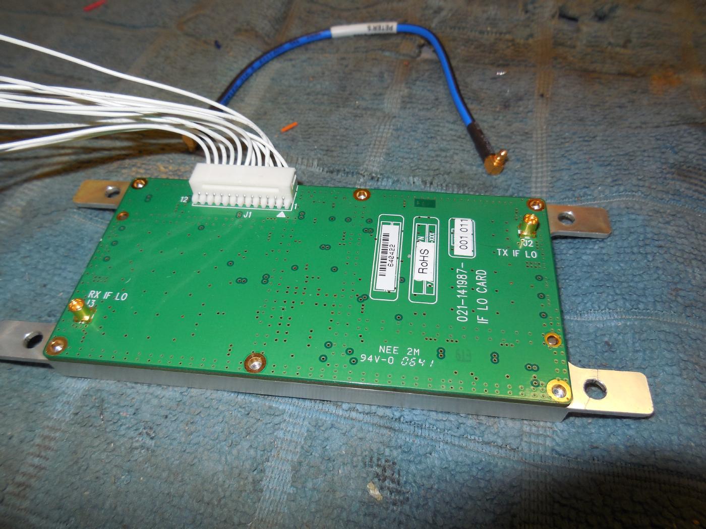
The oscillator board has a 12-pin header, connected via the white wires on the upper-left.
The pinout is as follows:
- TX LO Lock Alarm
- TX LO Load Enable
- Synthesizer Data
- Ground
- Synthesizer Clock
- Ground
- +5 VDC
- Ground
- +13.4 VDC
- Ground
- RX LO Load Enable
- RX LO Lock Alarm
The lock alarms are logic "high" on PLL lock, but are not used in this project.
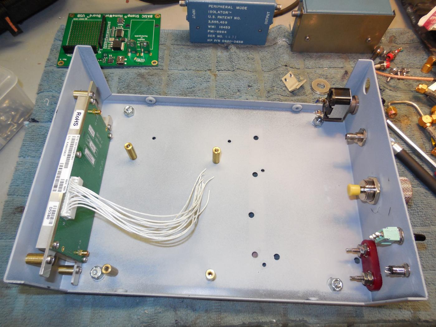
Placing the front-panel components in the case.
The oscillator board is mounted to the inside rear-panel using little standoffs.
A N female to SMA female bulkhead adapter is used for the main RF output signal.
SMA female bulkheads are used for the first LO input and -6 dB tap.
+15 VDC power is via the banana jacks.
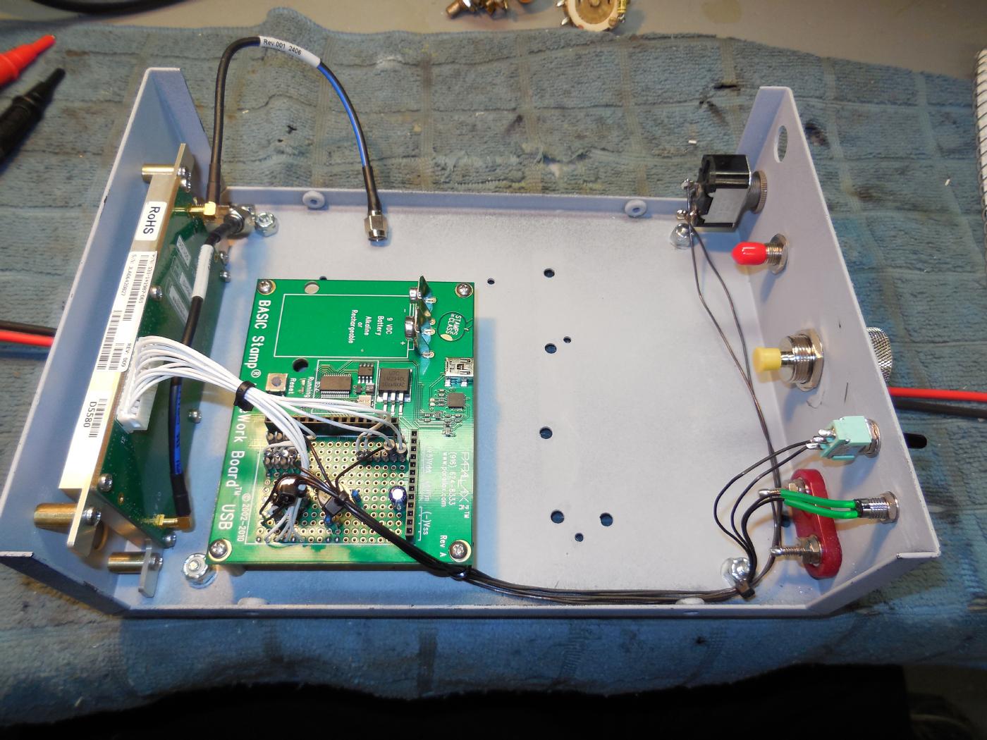
Adding the BASIC Stamp HomeWork Board USB.
Using a BASIC Stamp is a bit of overkill, but they are easy to program and you can now buy them at Radio Shack.
You can remove the HomeWork Board's stock breadboard with a razor blade and a little acetone.
The BASIC Stamp HomeWork Board is designed to run from a 9 volt battery, but the on-board voltage regulator will allow operation from a higher voltage power supply.
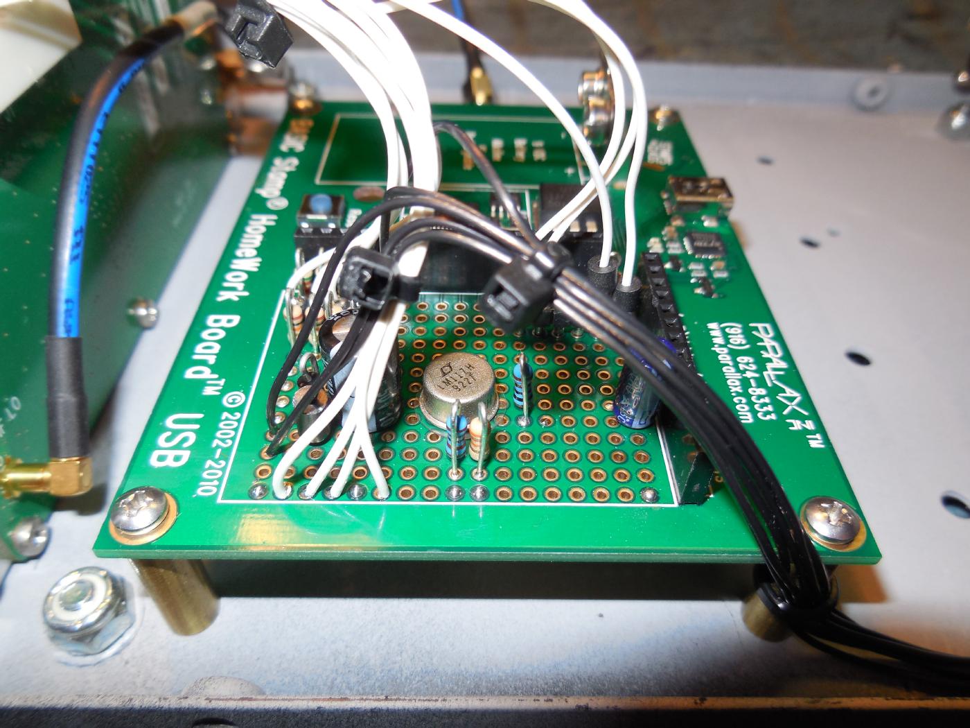
Close-up view of the LM317/LM117 voltage regulator for the Mini-Circuits DSN-2300A-1119+ frequency synthesizer.
I also added 22 µF capacitors on the BASIC Stamp's +5 VDC line.
The resistors for the LM317/LM117 should be 1% metal-film.
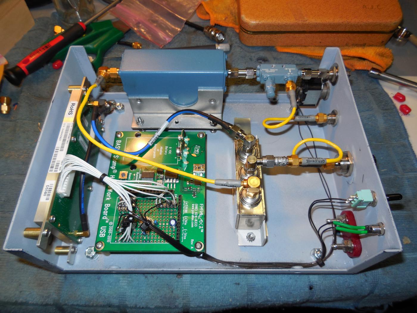
Overview of the completed tracking generator.
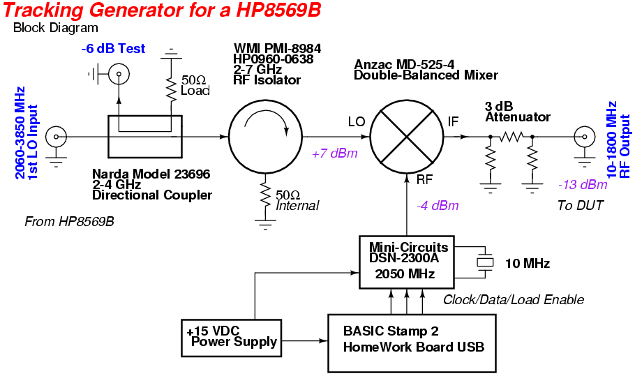
The 1st LO Input is along the top, via the directional coupler and isolator.
The key element in this tracking generator is a quality RF mixer which provides high isolation (40+ dB) between its LO/RF/IF ports.
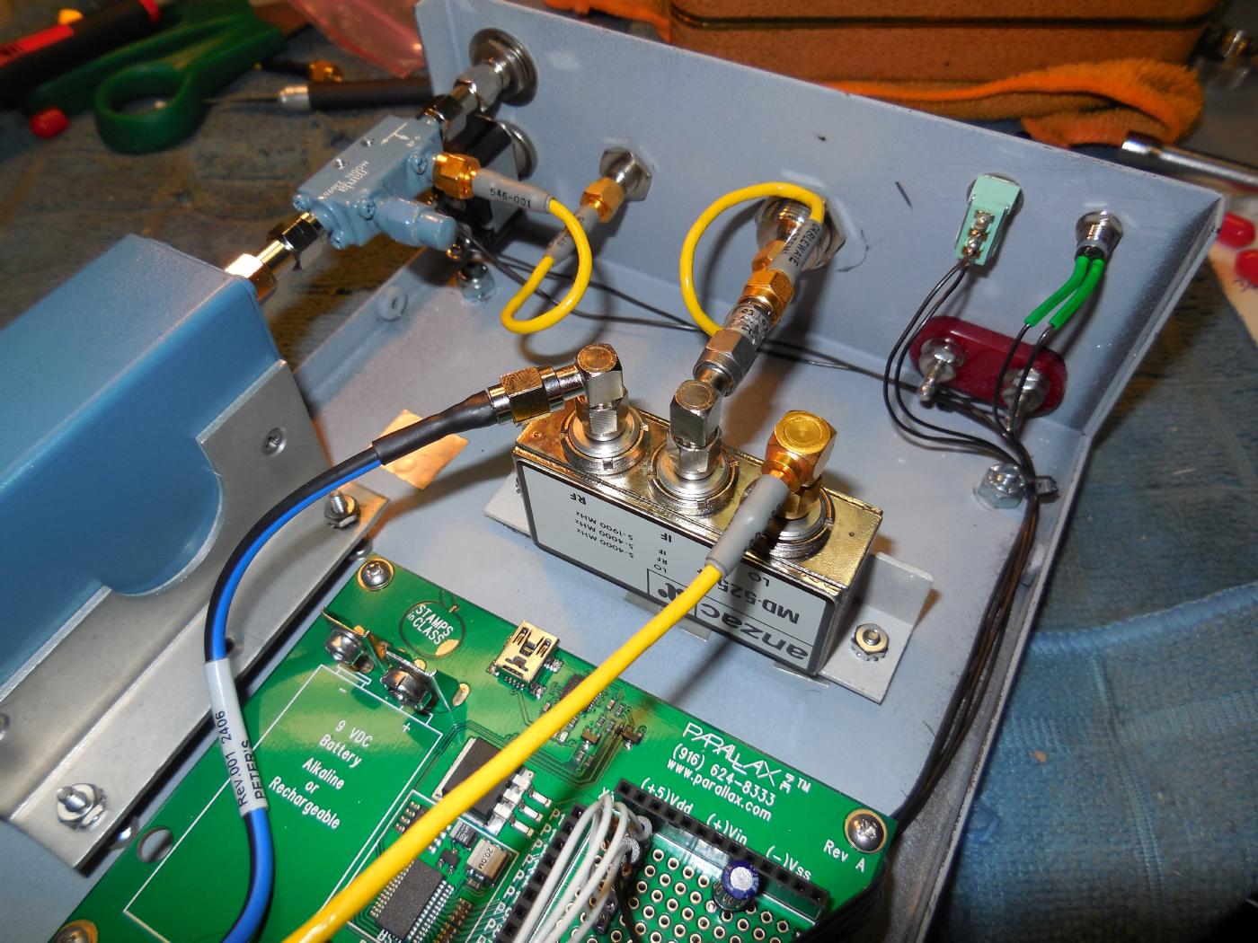
Used here is an Anzac MD-525 double-balanced mixer. The frequency range of its ports are LO: 5-4000 MHz, RF: 5-4000 MHz, IF: 5-1900 MHz. LO power should be around +7 dBm.
The 2050 MHz RF input signal to the mixer (left SMA) will be around -4 dBm. This level is somewhat arbitrary, but should be at least 10 dB lower than the LO signal for maxiumum dynamic range and to avoid generating mixer compression artifacts.
A 3 dB attenuator is on the MD-525's IF output port (center SMA) to force the mixer and spectrum analyzer to both see a 50 ohm impedance over their entire frequency ranges.
Ideally, there should also be a 2 GHz lowpass filter on the IF output to knock down any LO leakage and the harmonics, but we can get by without it for hobby use.
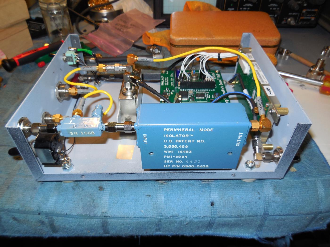
On the 1st LO Input (left) is an optional Narda Model 23696 2-4 GHz 6 dB directional coupler. This can be used to monitor the input LO frequency via a frequency counter to get a more accurate analyzer frequency readout.
The large, blue rectangle device is the Western Microwave PMI-8984 peripheral mode 20 dB isolator (HP0960-0638) which operates over the 2-7 GHz range.
This is also optional, but very useful for isolating the tracking generator from the spectrum analyzer to avoid creating spurious response artifacts.
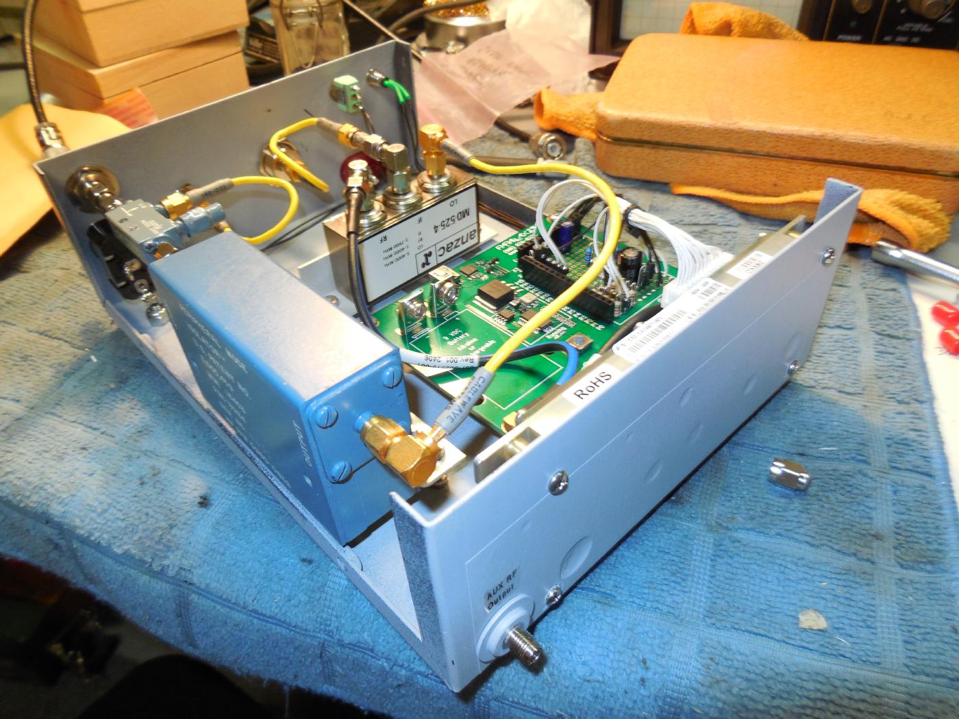
Auxiliary RF output SMA jack is on the rear.
This is an optional 1152 or 1250 MHz output at -4 dBm from the oscillator board.
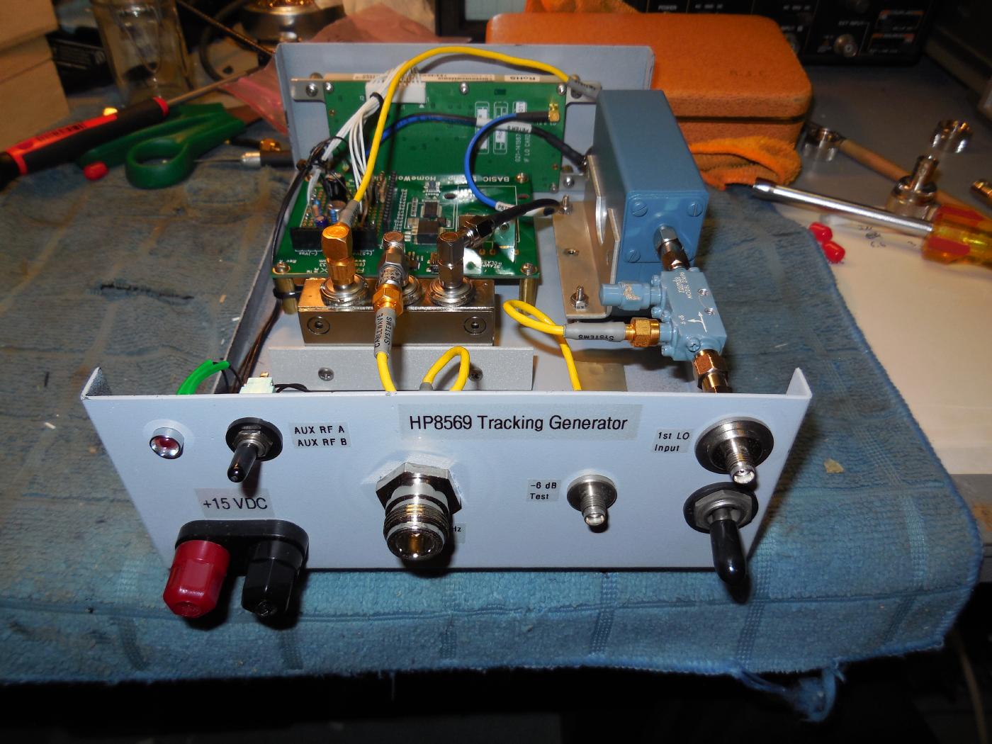
Front-panel overview of the completed HP8569 Tracking Generator project.
+15 VDC input is via the banana jacks on the lower-left. The current draw is minimal.
The upper-left red LED lights when the BASIC Stamp program finishes running.
The AUX RF A / AUX RF B SPST switch selects the optional auxiliary RF output frequency.
The N jack in the middle is the sweeping 10-1800 MHz RF Output.
The SMA jack next to the N connector is an optional -6 dB Test to measure the frequency of the first LO input.
The SMA jack on the upper-right is the 1st LO Input from the HP8569.
The switch on the lower-right is for main power.
Baseline system response test.
The RF output of the tracking generator is approximately -13 dBm (+/- 3 dB) over the 10-1800 MHz frequency range.
A straight-through coaxial cable is connected from the output of the tracking generator to the RF input of a HP8569B spectrum analyzer.
The 1st LO Output SMA jack on the HP8569B is connected to the 1st LO Input SMA jack on the tracking generator. This cable should be low-loss and well shielded to minimize RF leakage. The first LO on the HP8569B provides around +8 dBm of RF power.
The HP8569B is set to 0 dBm reference with 10 dB attenuation. The center frequency is around 500 MHz and the span is 100 MHz per horizontal division and 10 dB per vertical division. The "zero spur" is on the far-left.
Ideally, this response would be a perfectly straight line, but this requires the addition of a level-controlled output IF amplifier/attenuator which would increase the complexity of this project.
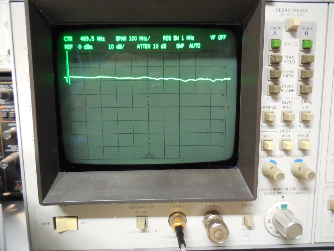
Close-up view of the baseline response.
This would represent an "ideal" connection with no loss.
HP spectrum analyzers with an INP-B->A function can "cancel out" any anomalies in the baseline system response.
Do this by first testing the baseline response with a high-quality, straight-through coaxial connection and storing the Trace B response by pressing STORE BLANK.
Connect the device to test then press the INP-B->A button.
This "subtracts" the baseline response anomalies from the current input to show only the response of the DUT.
You'll need to redo this "cancelling" technique everytime you change the analyzer's display functions or swap out cables.
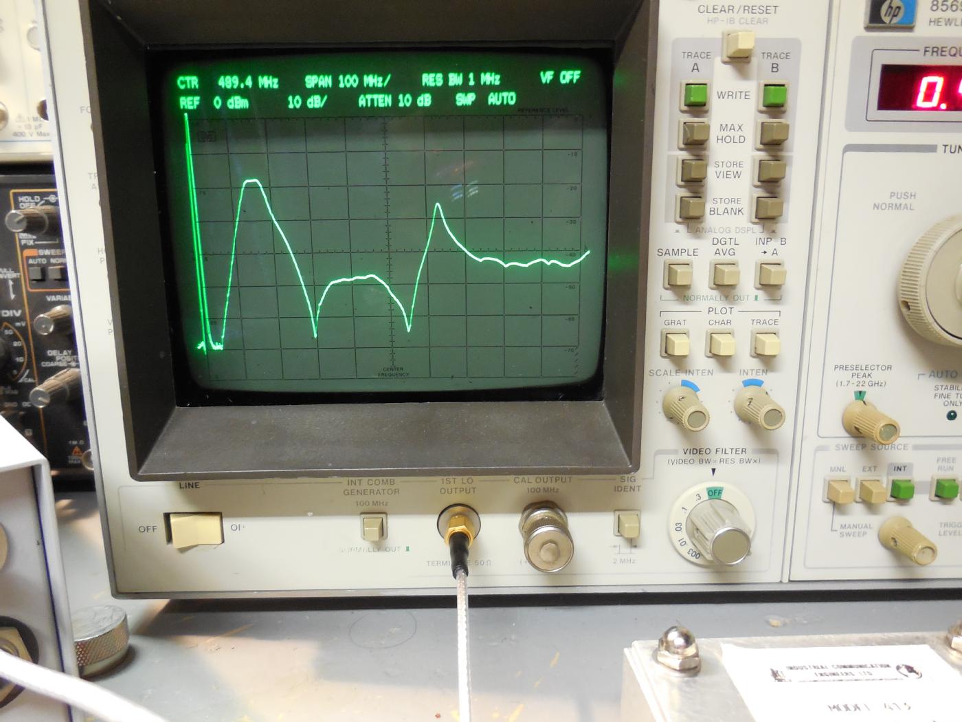
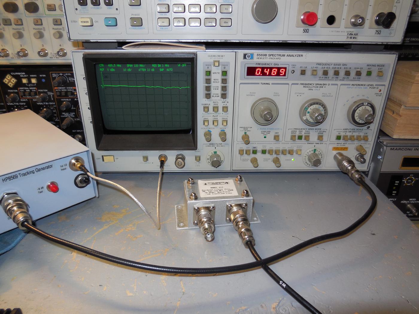
Testing a Industrial Communication Engineers, Ltd. Model 413 bandpass filter (144-148 MHz).
The center frequency is still around 500 MHz and the span is 100 MHz per horizontal division and 10 dB per vertical division.
The 3 dB points of this filter are around 110 and 170 MHz. The "spike" on the right is around 621 MHz.
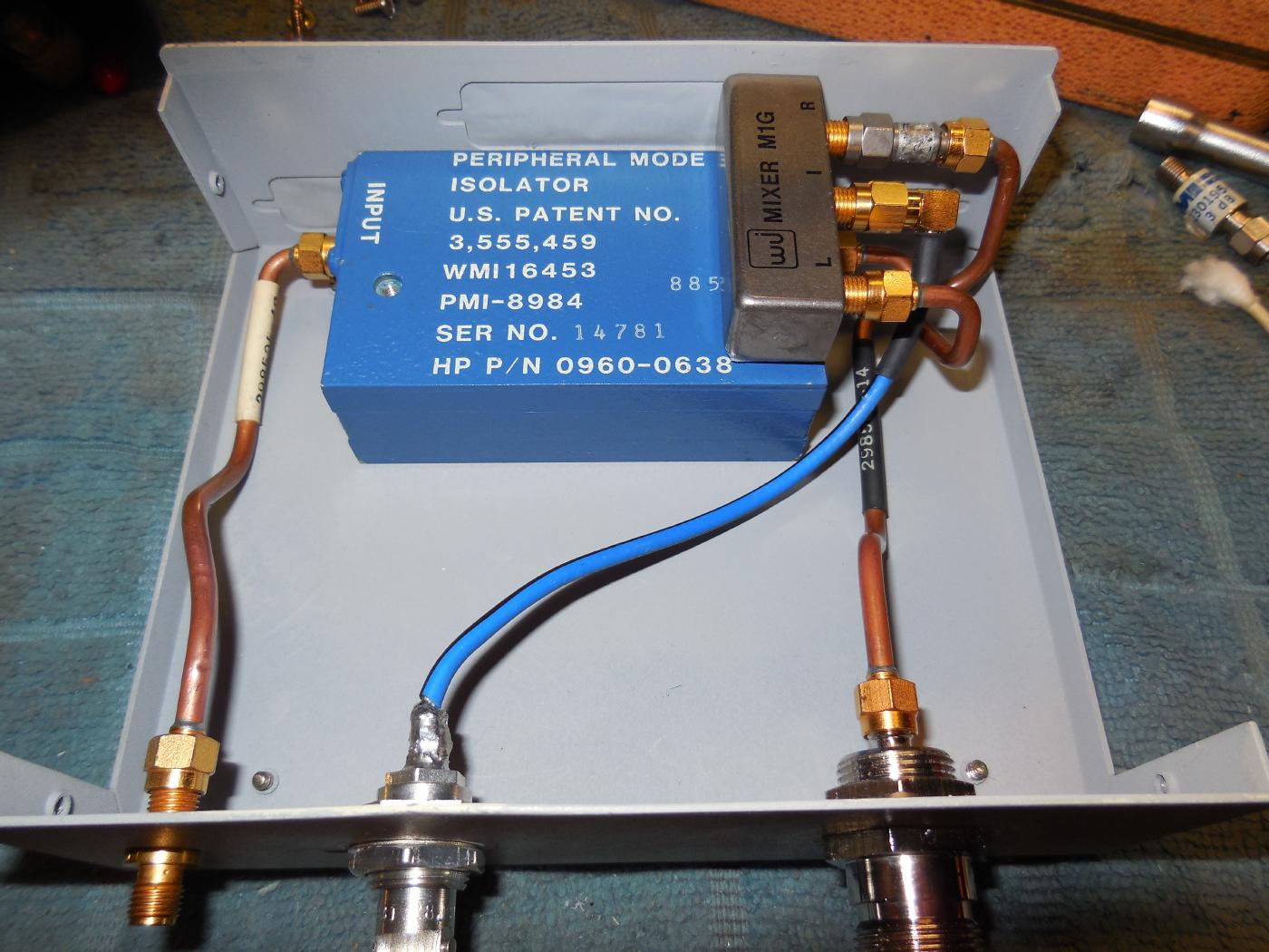
Experimental tracking generator for the 1700-4100 MHz range.
In this mode, the HP8569B's sweeping first LO signal (2021.4-4421.4 MHz) is mixed with an external 321.4 MHz signal to generate a tracking 1700-4100 MHz output.
The mixer is a Watkins-Johnson M1G double-balanced mixer. It requires +7 dBm of LO power and has around 40 dB of port isolation. The LO/RF ports can operate over the 1000-4200 MHz range.
The M1G's LO port has a Western Microwave PMI-8984 peripheral mode isolator on its input for additional isolation.
The M1G's IF port is used for the 321.4 MHz input, which is at around -4 dBm and is supplied via an external RF signal generator.
The RF port is then the sweeping 1700-4100 MHz output. There is a high-quality 3 dB attenuator on the RF port.
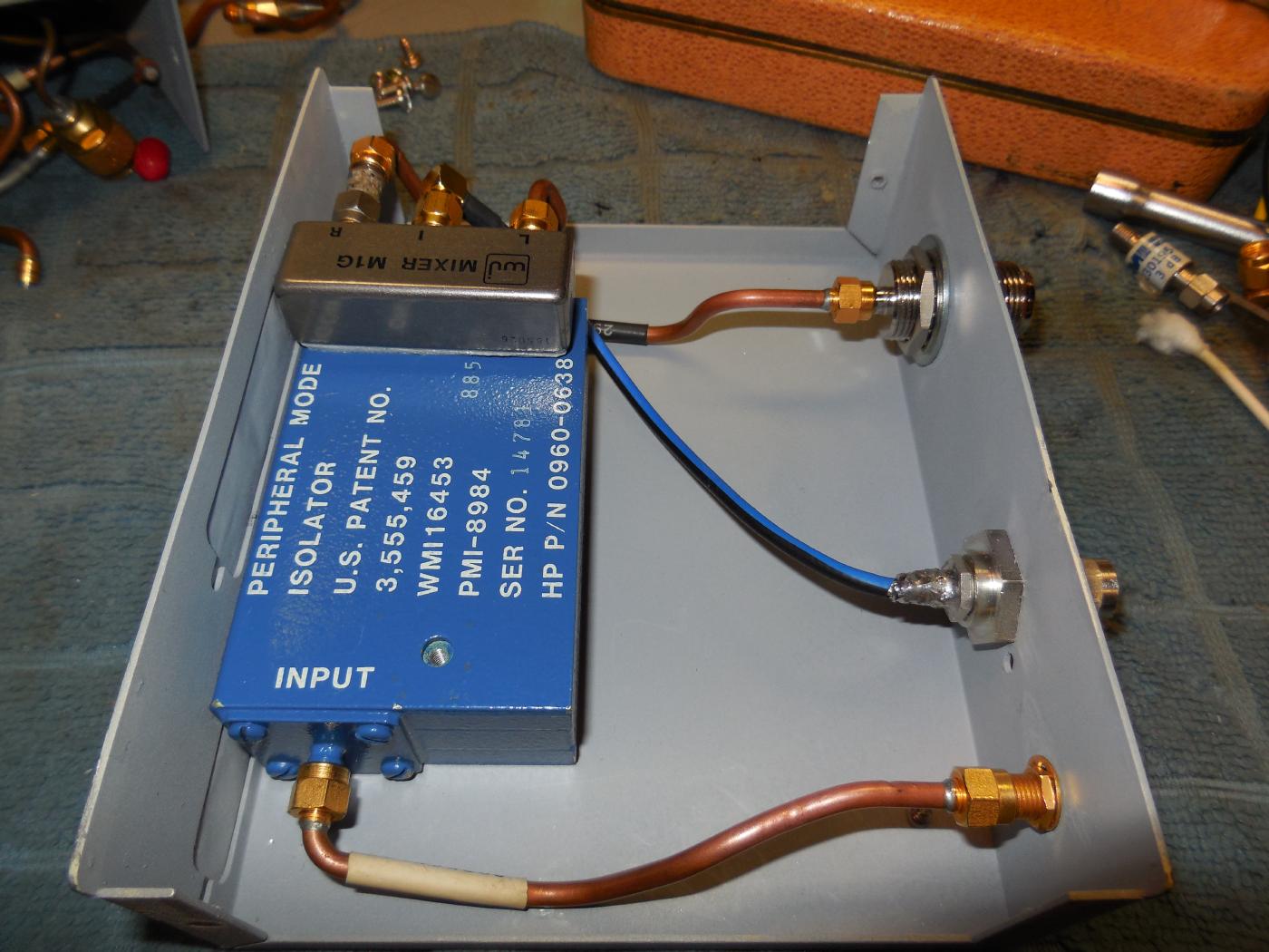
Alternate view.
The SMA jack is for the 1st LO Input.
The BNC jack is for the 321.4 MHz Input.
The N jack is for the sweeping 1700-4100 MHz Output.
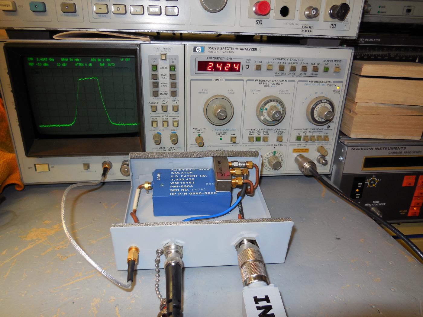
1700-4100 MHz tracking generator in operation.
Displayed is a sweep of a commercial 2.4 GHz bandpass filter.
The HP8569B's center frequency is around 2.424 GHz and the span is 50 MHz per horizontal division. Vertical span is 10 dB per division.