Divide-by-8 prescaler which is good up to 13+ GHz.
Overview
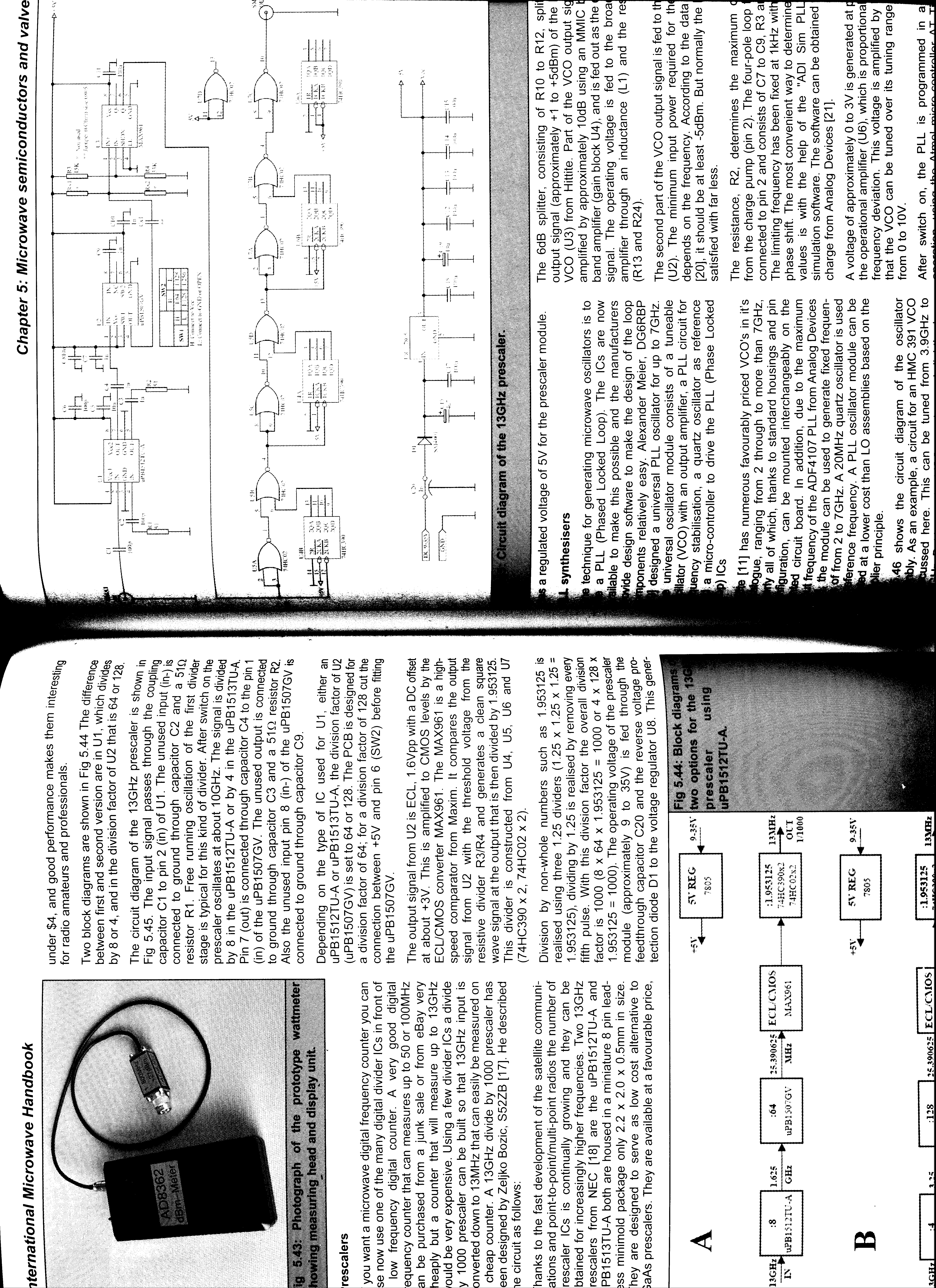
Here is a fairly simple "divide-by-1000" circuit which was first designed by Zeljko Bozic, S52ZB, in a 2006 issue of VHF Communications Magazine. The idea of this project is to extend the range of older (and cheaper) frequency counters. You can often find 100 MHz frequency counters for as little as $20 at hamfests or eBay, and this simple circuit will extend their range up to at least 13 GHz.
This version is based around a Hittite HMC363 divide-by-8 prescaler, a Fujitsu MB506 divide-by-64 prescaler, and a "divide-by-1.953125" circuit using standard digital logic. The Hittite HMC363 front-end prescaler is good up to 13 GHz or so, and will do 15 GHz if you increase the input RF power a bit and minimize the prescaler's exposure time.
It's possible to pick up the Hittite HMC363 evaluation board for around $100, or you may be able to receive a couple HMC363s as free samples. The evaluation board will be ideal, as it's properly designed for high-frequency microwave work. The Fujitsu MB506 can be found in some MMDS or satellite TV downconverters, the Fujitsu MB501 can probably be substituted with a slight circuit change. Fujitsu MB501 prescalers can be found in older analog cellular phones. The rest of the circuit is just a simple ECL-to-CMOS logic converter using a Maxim MAX961 high-speed comparator, and some 74HC390 ripple-counters and 74HC02 NOR-gate logic chips wired up as a divider. The output of the Fujitsu MB506 is in Emitter-Coupled Logic (ECL), which means the signal is 1.6 volts peak-to-peak with a DC offset of around 3 volts. The Maxim MAX961 compares this signal to a preset reference DC voltage and converts the signal into one with the normal +5/0 volts that we're used to.
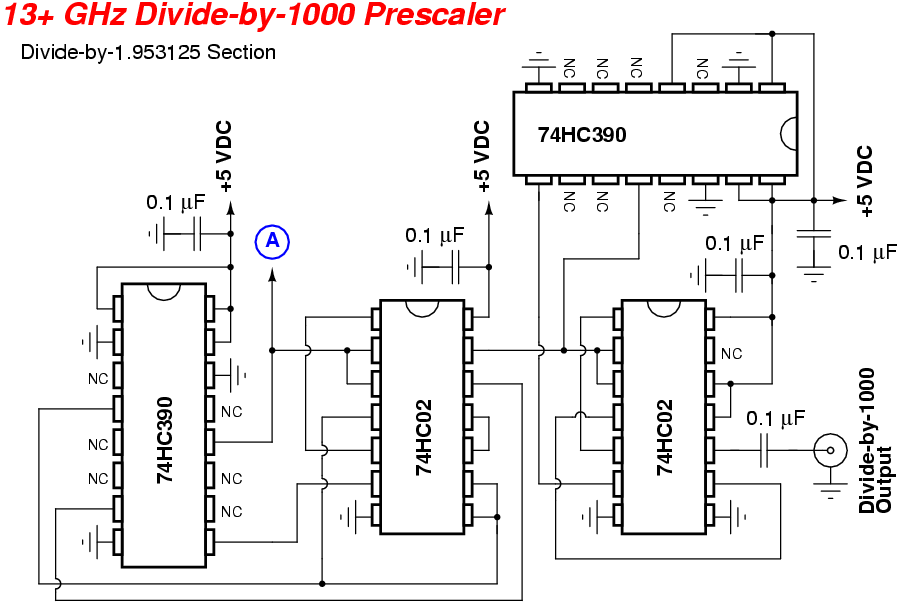
The "divide-by-1.953125" circuit is based around the fact that by using three "divide-by-1.25" circuits you can effectivly divide by 1.953125 (1.25 x 1.25 x 1.25 = 1.953125). Dividing by non-whole numbers comes about by removing certain pulses in the divider chain.
Hittite HMC363 Evaluation Board Schematic
Divide-by-8 prescaler which is good up to 13+ GHz.
Pictures & Construction Notes
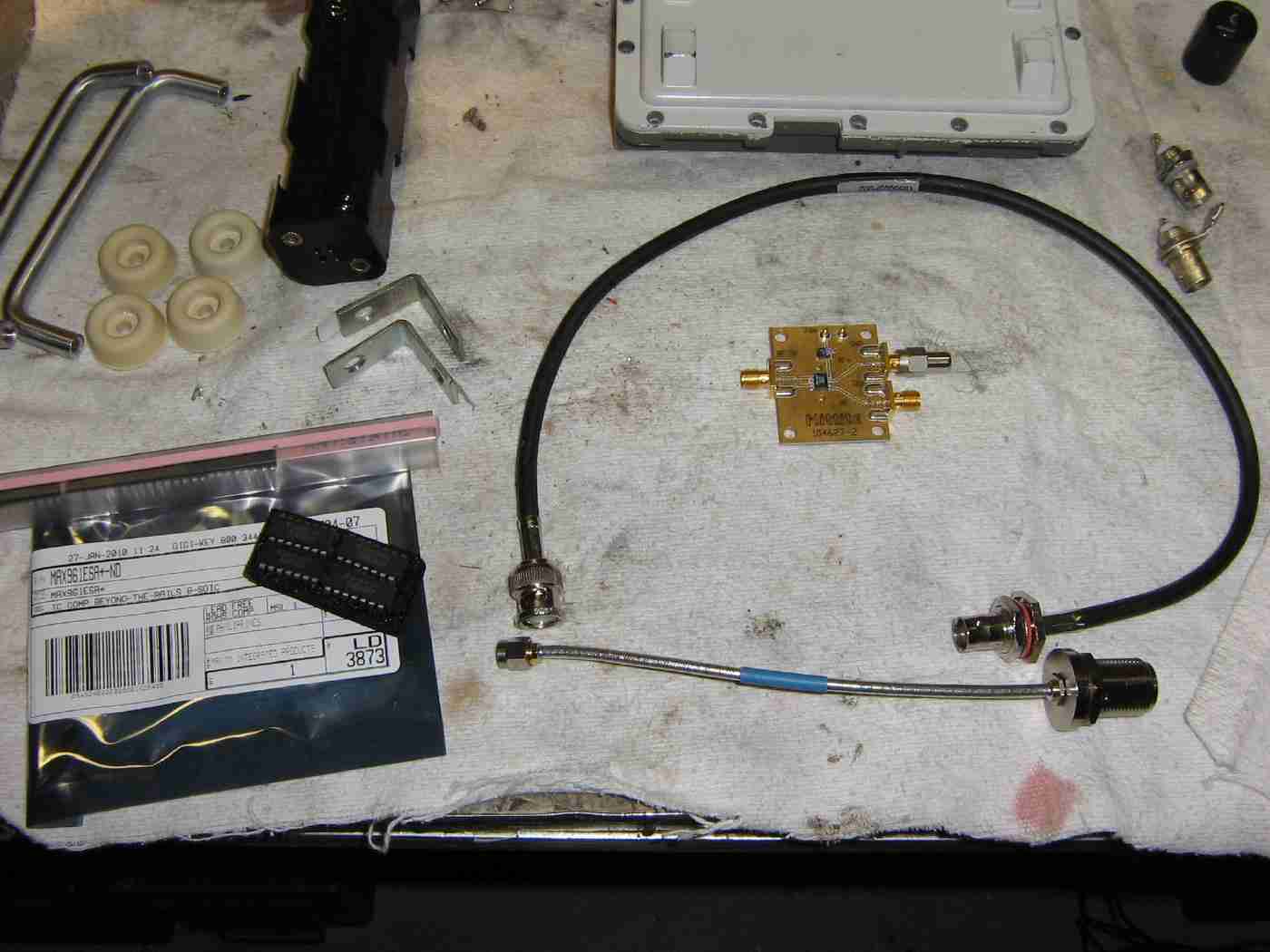
Overview of the items used in this project.
The Hittite HMC363 evaluation board is in the middle, an old California Amplifier downconverter case (upper-right) will hold the rest of the digital logic. Panel-mount N and BNC connectors will be for the RF input and prescaler output. The circuit will be powered via eight "AA" batteries (+12 VDC) in a standard holder available at Radio Shack.
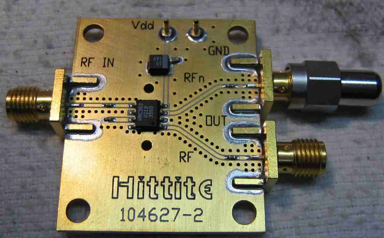
Closeup of the Hittite HMC363 evaluation board.
The board has two "divide-by-8" prescaler outputs so one will need to be terminated with 50 ohm load.
The board requires +5 VDC (Vdd) at around 70 mA.
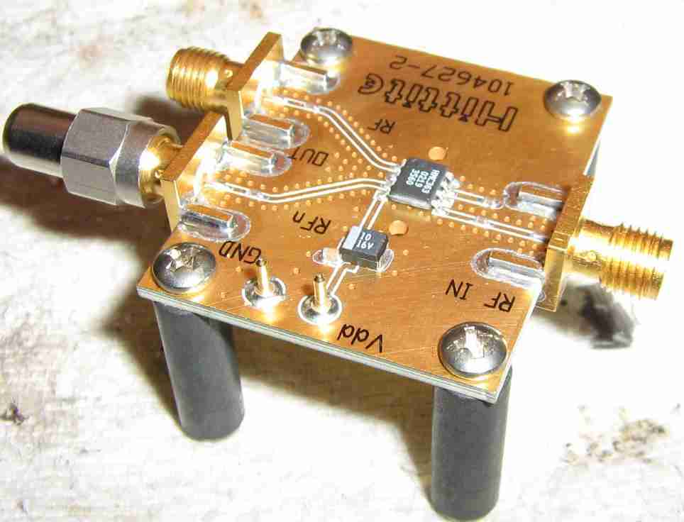
Alternate view of the Hittite HMC363 evaluation board mounted on threaded stand-offs.
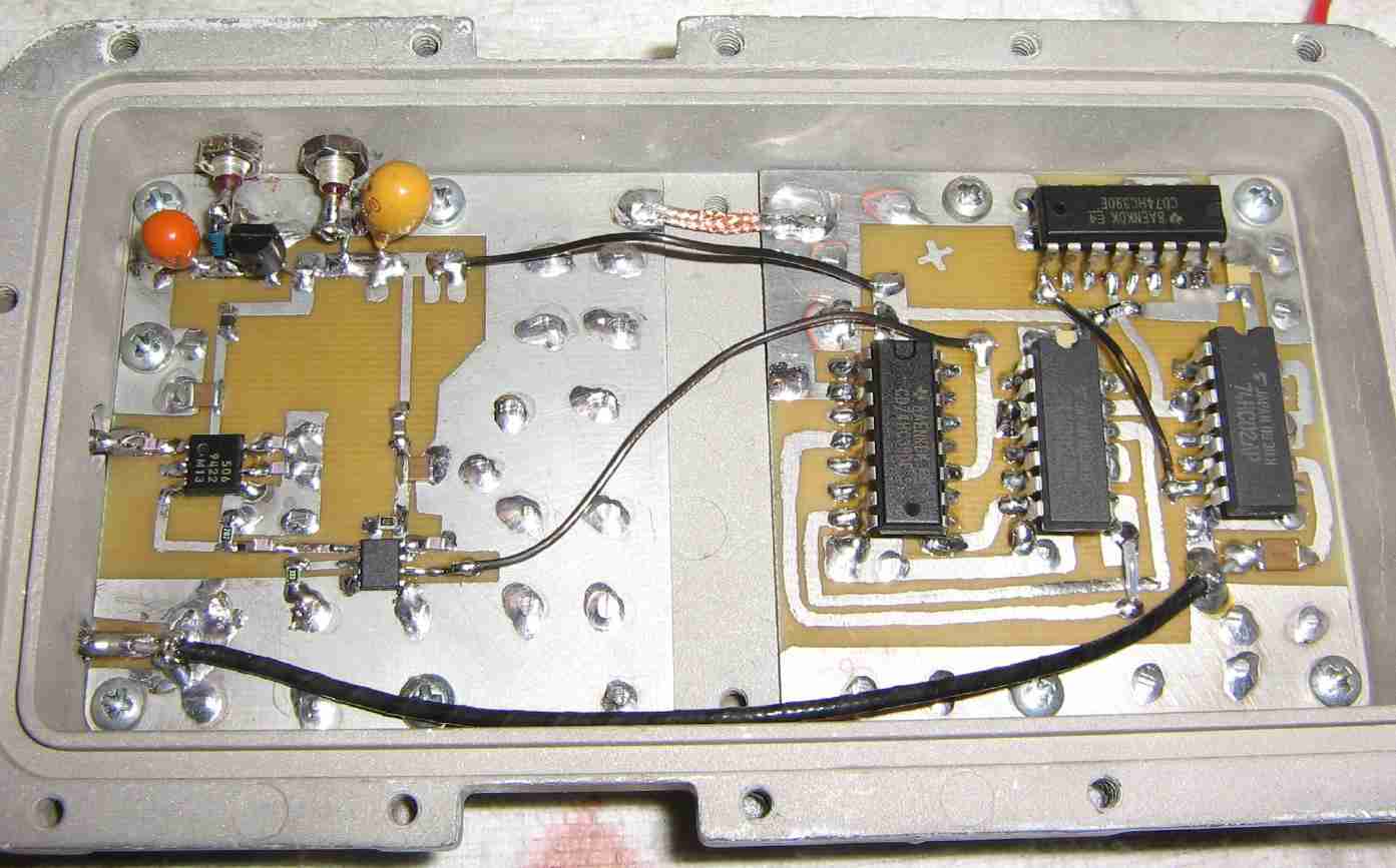
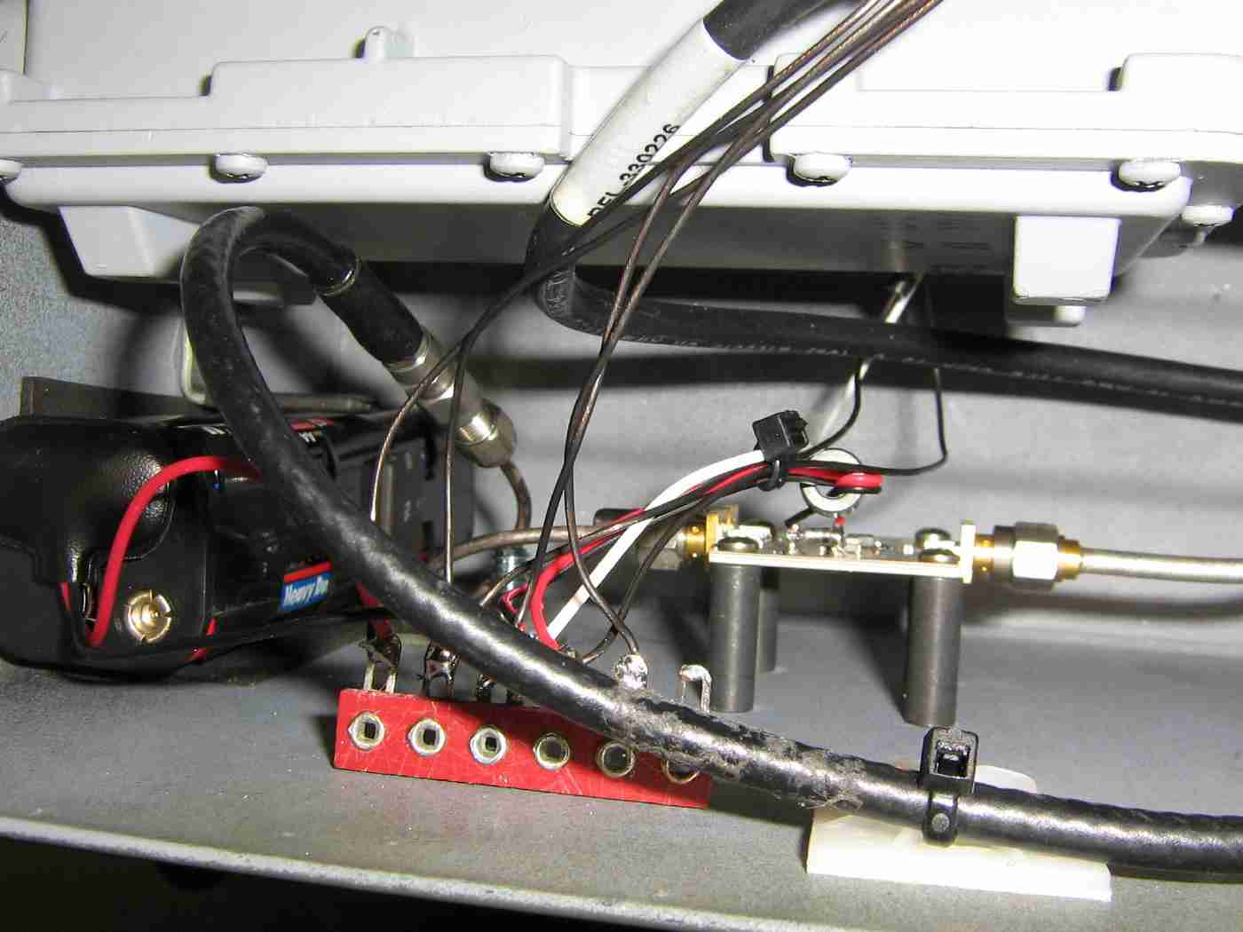
Overview of the Fujitsu MB506 divide-by-64 prescaler and the digital logic for the divide-by-1.953125 circuit.
The +12 VDC comes in to the 78L05 voltage regulator via the 1000 pF feed-through capacitor on the upper-left. The other feed-through capacitor provides a clean +5 VDC source to supply the Hittite HMC363 evaluation board.
In the middle-left, is the Fujitsu MB506 prescaler fed via a BNC jack attached to the downconverter case. The 8-pin SMT part to the lower-right of the MB506 is the Maxim MAX961 comparator. On the right-side are the two 74HC390 ripple-counters and 74HC02 two-input NOR gates.
The final "divide-by-1000" signal passes through a 0.1 µF capacitor via a short piece of RG-174 coax to a BNC jack on the lower-left.
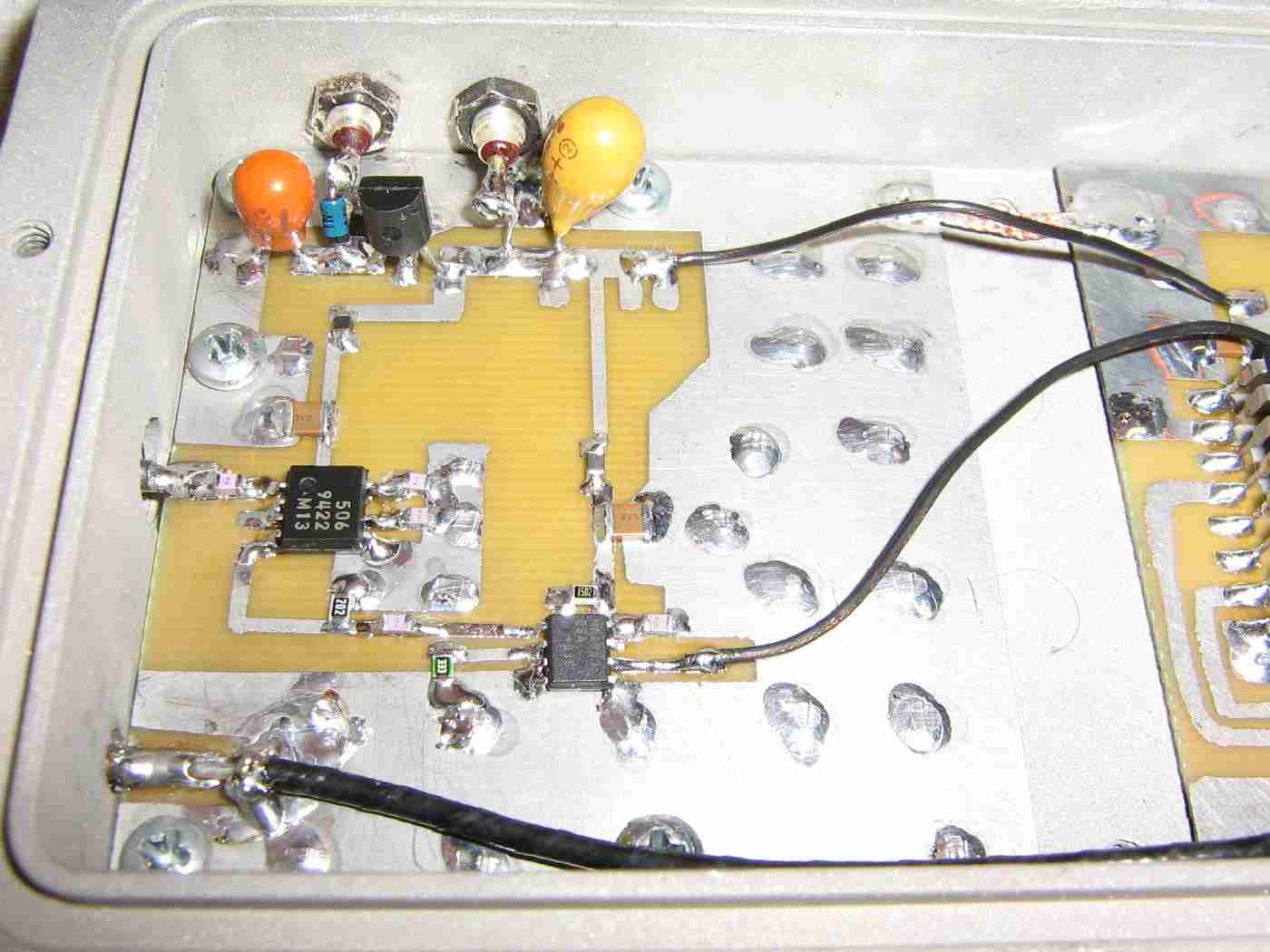
Closeup view of the 78L05 voltage regulator, Fujitsu MB506 prescaler, and Maxim MAX961 high-speed comparator.
The maximum input to the Fujitsu MB506 prescaler will be around 1.6 GHz, so proper microwave construction techniques will need to be used for that IC. Everything else can be handled as regular low-frequency signals.
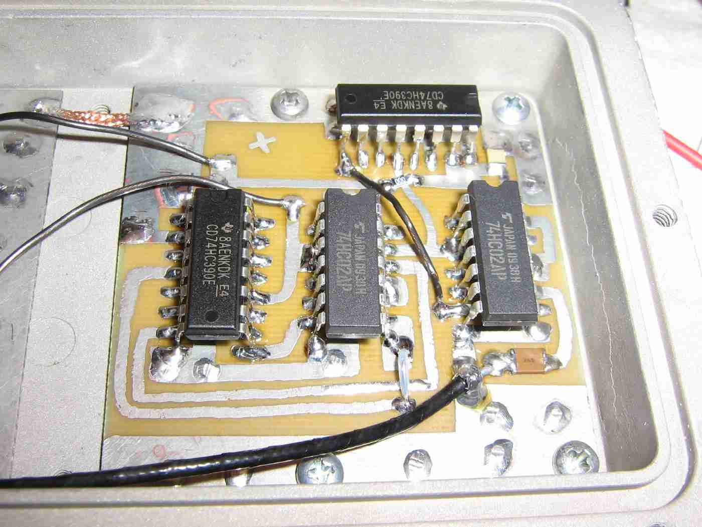
Closeup view of the two 74HC390 ripple-counters and 74HC02 two-input NOR gates.
The output of the MAX961 is the incoming wire soldered in the middle.
The other incoming wire is for +5 VDC.
Mounting the HMC363 evaluation board and battery pack in an old ammo can.
A solder terminal strip will allow for single-point wiring.
A small ferrite bead was slipped over the power wires to the Hittite HMC363 evaluation board.
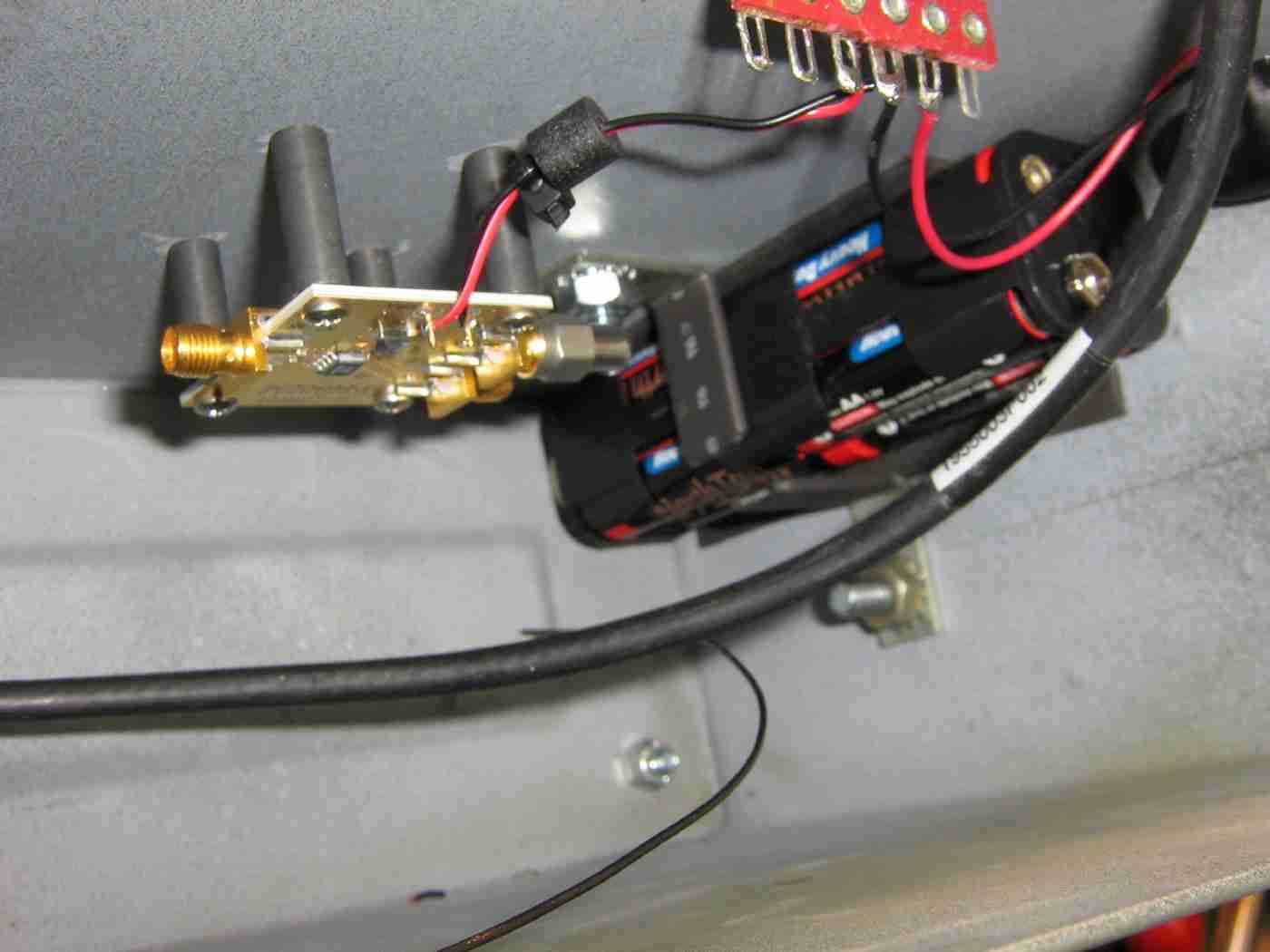
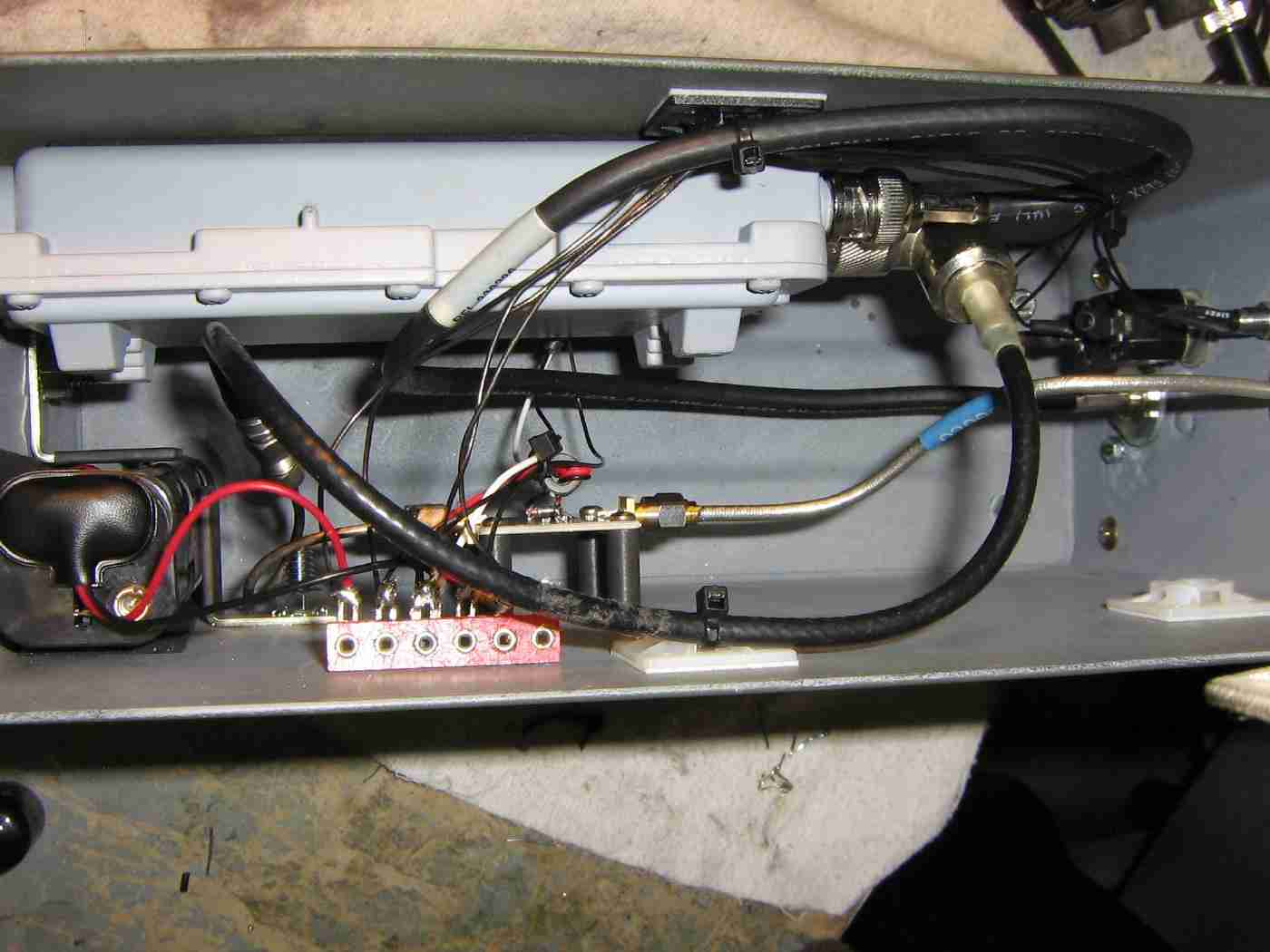
Mounting the MMDS downconverter case to the side of the ammo can and attaching the incoming RF cables.
There is a little SMA jumper cable on the output of the HMC363 evaluation board.
Finished overall view.
The front-panel of the ammo can holds the panel-mounted N and BNC connectors as well as the power switch and a power-indicating LED.
High-quality conformable coax is used on the HMC363's RF input due to its better support for frequencies above 10 GHz. The rest of the RF cables can be standard RG-58, or equivalent, as they will be carrying lower frequency signals. Do try to use high-quality coax and connectors throughout this project to avoid signal leakage or receiving external RF signals.
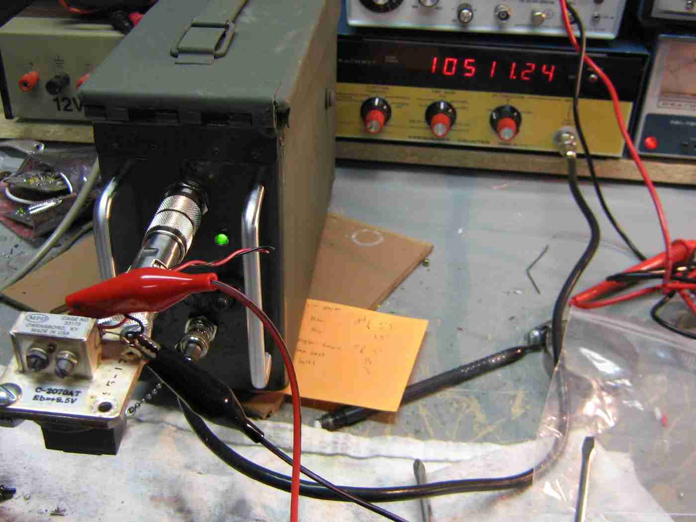
Divide-by-1000 prescaler in operation.
The output is displayed on a Heathkit IM-4110 100 MHz frequency counter.
The frequency counter is reading "10.51124 MHz" for a final RF input frequency of 10.51124 GHz. This signal was a Gunn diode source from a stock MPH Industries K55 X-band police radar with a WR-90 to N adapter. The output from this Gunn diode source is around +14 dBm (25 mW), so a 10 dB attenuator was added to the input of the prescaler to knock the signal down a bit.
Schematics
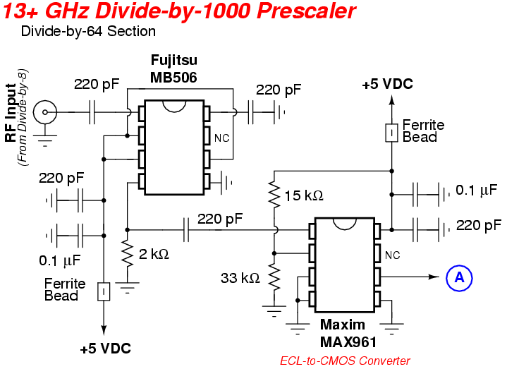
- 13 GHz Frequency Counter Prescaler - Schematic #1 Divide-by-64 section.
- 13 GHz Frequency Counter Prescaler - Schematic #2 Divide-by-1.953125 section.
- ExpressPCB Pattern Main divider board except for the Hittite prescaler, untested. (PDF Version)
Notes / Datasheets
- Fujitsu MB506 Prescaler (65k PDF)
- Hittite HMC363 Divide-by-8 Prescaler (243k PDF)
- Maxim MAX961 Comparator (321k PDF)
- 74HC390 Dual-Decade Ripple Counter (51k PDF)
- 74HC02 Quad 2-Input NOR Gate (103k PDF)
- GBPPR Divide-by-1000 3.5 GHz Prescaler Similar "divide-by-1000" prescaler using an easier to find prescaler IC.
- Divide-by-1000 13 GHz Prescaler by Zeljko Bozic, S52ZB
- EI9GG Frequency Counter 10 MHz frequency counter accurate to 1 Hz.
Return to Green Bay Professional Packet Radio for more info and contact information.