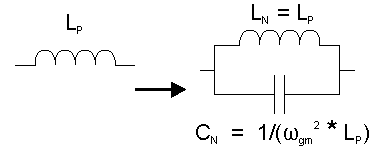
A translation from a low pass prototype to a band stop filter requires three steps. The first of which is to do a resistance translation (q.v.) and second to do a high pass frequency translation using this conversion factor. ![]() Be warned that the corner frequencies mentioned are not down at the bottom of the band stop curve. The corner frequencies are at the 3 dB down points on the curve. Go to Help-Data Entry-Band Stop in the main menu. |
Having done those two translations, find the geometric mean of the two frequencies f uc and f lc by using ![]() The geometric mean and the arithmetic mean are only a few percentage points different when pass bandwidths are small, but can become large when bandwidths increase. |
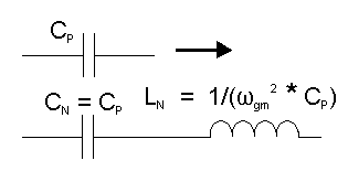
To complete the bandstop transformation, each capacitor becomes a series resonant circuit which is resonant at the geometric mean frequency. Each inductor becomes a parallel resonant circuit which is resonant at the geometric mean frequency. To translate from the previously prepared capacitance values, perform this mathematical manipulation: ![]() |
To translate from the previously prepared inductance values to the parallel resonant circuit, perform this mathematical manipulation: ![]() |
With band stop filters, the interest is in attenuating a range of frequencies from a to b at the 3 dB level and a second range of frequencies from c to d at a greater attenuation. Conceptually, first consider the range c to d first as in "I really need to lower the television channel 2 (54 MHz to 60 MHz) interference by about 20 dB." Consider a second band where the attenuation is at the 3 dB level. Perhaps the band could be from 50 MHz to 64 MHz where a third order filter would do nicely. Band stop filters have a deep "V" shape and the deepest point of the V is not located at the arithmetic mean of the band specified. |
If a single frequency is the problem, the deepest part of the V must be at that frequency. The Butterworth Calculator gives the option of selecting "Notch" which will place the deepest part of the V and the greatest attenuation on that frequency. Select some accompanying bandwidths for purposes of selecting the order. Higher orders will give deeper notches. Without doing a simulation, the attenuation at the bottom of the notch remains unknown. A recent simulation showed an attenuation in excess of 550 dB when using a thirteenth order filter, which gives no realistic information. |
The band stop bandwidth is at the 3 dB down point on the band stop filter's curve. A second bandwidth, which the Butterworth Calculator designates the "attenuation bandwidth" is narrower and located at greater attenuation points on the band stop graph. Please visit Help-Data Entry-Band Stop in the main menu.