 |
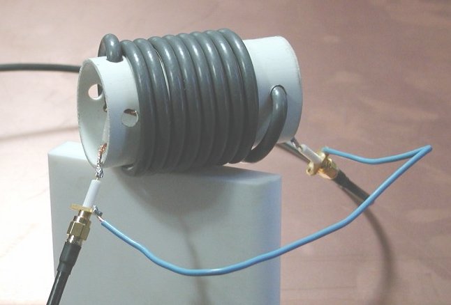
| The VNA with two 24 inch cables connected (the fixture) and a tuned circuit (devise under test)
soldered to the SMA connectors. The vna has SMA connectors on it and TenTec supplies SMA items for the
detector calibration and fixture calibration procedures. You will need to supply a few SMA connectors
in order to build test fixtures, such as the two SMA solder tail connectors used for the LC test pictured
here. This test instrument is not for "appliance operators", I "read the fine manual" through twice before
getting started and still had a couple of minor snafu's before getting up to speed. Careful reading of the
manual will pay dividends! |
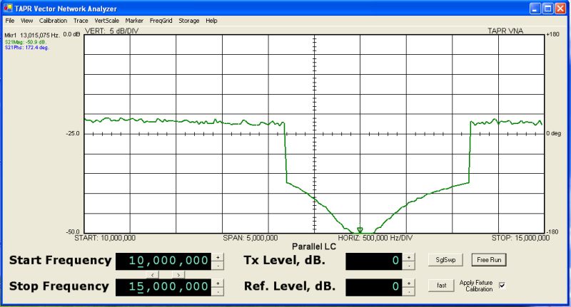 |
| A trace of S21 magnitude shows the deep (-50.9 db) stop band (characteristic of a parallel tuned
circuit) centered at 13MHz. |
 |
| The same components, wired in series this time, show the characteristic series LC passband centered at
6.085MHz. |
 |
| This tool makes tuning traps fun. The trap in the picture is a coaxial coil style of trap made for
a 40/20 dual band trap dipole built for a friend. |
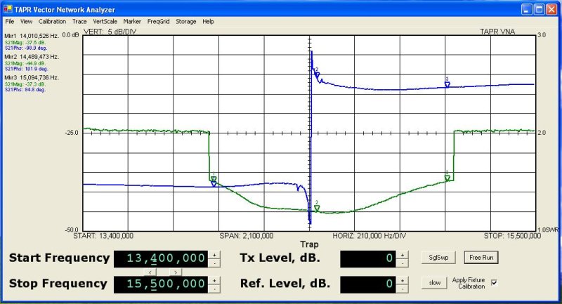 |
| I did not even try to predict the proper length of cable for the trap, a left over length of coax from another
project just happened to be 40" long so I wound the trap, did a wide sweep with the analyzer and then
trimmed the coax until the stop band settled at 20 meters. The useful portion of the stop band for this style
of trap is a full one MHz wide. |
 |
| Here is a look at my homebrew 4 element 6 meter beam at 40 feet (including 60 feet of feed line). The orange
trace is the S11 return loss and the red trace is SWR. |
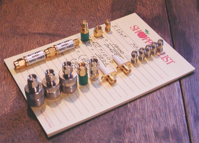 |
The items in the back row (along with a 1 meter cable and a 3 meter cable) come with the VNA from TenTec
(they are manufactured by L-Com), the items in the front row I bought to allow some flexibility in fixture
setup.
|