Multi-function Amateur Radio Controller
FoxBox
DTMF Decoder
DTMF Controller
CW Keyer
Auto Pager
By N6ZAV and N6BG
Marty Mitchell, N6ZAV          Byon Garrabrant, N6BG
P.O. Box 10413                 8128 Kokoma Dr.
Costa Mesa, CA  92627          Las Vegas, NV 89128
   (714)760-6060
T-Hunts are fun, but talking continuously for 4 hours as the hidden transmitter can be a real drag. The FoxBox Controller provides your radio with tone sequences, PTT control and CW ID. There are several tone sequences and duty-cycles to choose from, and you can even talk through the hidden transmitter if you are using a dual-band radio. CW ID occurs at least once every 10 minutes, so the FoxBox can be left to run for hours on end. It can be remotely secured to prevent others from controlling it. Callsign, tone sequences, duty cycles, password and CW speed can be reprogrammed easily with DTMF tones.
The DTMF decoder will decode any incoming DTMF tones to your computer for easy viewing or logging. Simply patch your radio's speaker output to RaCon's 1/8" audio jack and any DTMF tones received will be displayed on your computer monitor. This feature can be used to verify proper operation of DTMF transmitters, to log DTMF activity, or to remotely control your computer using DTMF tones.
The DTMF controller provides a simple way to remotely control external devices with DTMF tones. By mating a relay card or CMOS compatible switch to RaCon's data port, simple DTMF sequences provide you with complete control of 8 independent functions. You may wish to use this feature to control equipment in your ham shack, car or remote radio site. RaCon can also transmit a bit status report using low and high tones followed by CW ID.
The CW Keyer, when plugged into your computer via the serial port and your HT via the radio port, will send Morse Code over the air in MCW (Modulated CW) form. RaCon 6805 manages the pushing and releasing of the PTT at the proper times, so all you do is type on your keyboard. A menu allows users to select both character and word speed independently (Farnsworth). This would be useful for sending practice Morse code exams over the air, or improving your code speed by engaging in an MCW QSO with a friend.
The Auto-pager configuration provides a convenient way to page your pager-equipped ham friends by radio without using an autopatch. Connect RaCon 6805 to a receiver and an external modem at your home. By transmitting the proper DTMF codes on simplex or a repeater (with trustee's permission), the modem will dial one of four pager numbers and send one of four messages. By connecting RaCon's serial port to a computer, pager numbers and messages are configurable. This feature can be used to expedite RACES, ARES, Red Cross and other emergency call-outs.
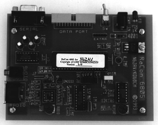
RaCon 6805 has a 16-bit data port for hardware upgradability.
The kit comes complete with all parts necessary to build the
board minus chassis. It runs off any 7-35 VDC source and only
draws 30 ma., so a 9V battery will work, or better yet, (8) AA
cells. Assembly time should be less than two hours.
All components should be inserted from the component silk-screen
side of the board. The integrated circuits are static sensitive.
Use standard precautions when handling these devices. Diodes,
transistors, some capacitors and all integrated circuits are polarity
critical. Be sure to orient these components properly prior to
installation. A low wattage soldering iron (15-25 watts) with
a small tip is preferable. You will also need some thin solder,
small diagonal cutters and a pair of needle nose pliers. See
PARTS LIST for resistor color code and capacitor identification
information. Trim leads of components AFTER soldering in place.
Silkscreen values ending with "MF" are capacitors and
those ending with "K" or "M" are resistors
(".01MF" is a capacitor and "10K" is a resistor).
Detail Instructions
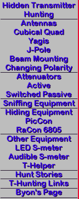
Prepare power and interface cables as required by desired applications. See INTERFACE CABLES for more on this.
Do not insert any integrated circuits until the following check-out
procedure is complete.
To adjust the proper REPEAT level, select the audio repeat mode
(see below), and adjust both receiver volume and RaCon REPEAT
pot for a comfortable level on a third radio. Verify that the
DTMF decoder is still functional at the new receiver volume level.

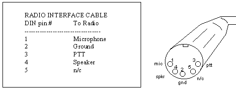
Note the unusual sequence in which DIN pins are numbered. The
radio side of this cable varies between radio manufacturers.
Consult your radio owners manual for details.
Data Port
Use a 26 pin female ribbon cable connector with ribbon cable to
mate with RaCon's data port. You may wish to build your own cable
or buy a pre-built one. Here is a table of signals and their
corresponding pin numbers. Pin 1 is usually marked on both connectors
with a small triangle. All signals may not be used at this time.
                DATA PORT
 Pin # Signal  Pin # Signal  Pin # Signal
 ----------------------------------------
    1  Y8        10  +5v       19 Gnd
    2  Y7        11  X1        20 +5v
    3  Y6        12  X2        21 IRQ
    4  Y5        13  X3        22 EXTRA
    5  Y4        14  X4        23 EXTRA
    6  Y3        15  X5        24 EXTRA
    7  Y2        16  X6        25 EXTRA
    8  Y1        17  X7        26 EXTRA
    9  Gnd       18  X8
MODE            PRIOR TO POWER UP  AFTER POWER UP
                   JUMPER  J8
                   D  C  B  A       DTMF  SERIAL
----------------------------------------------
FoxBox                      X         1      1
FoxBox-Single band       X            2      2
DTMF Decoder             X  X         3      3
DTMF Controller       X               4      4
CW Keyer              X     X         5      5
Auto Pager            X  X            6      6
Select by DTMF                       n/a    n/a
  or Serial
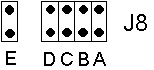
Set jumper J8 A-D for desired power-up configuration. Jumper J8-E is used within some of the features, such as the FoxBox change callsign, sequence and transmission. For DTMF or serial mode selection, remove jumper shunts A-D. This is useful while experimenting with multiple modes because it does not require repeated access to jumper J8. For single mode usage, you may find that mode selection using jumper J8 is more convenient because it does not require a DTMF or serial command upon power-up.
To operate under a different mode, power must be cycled before the new mode can be selected.
The serial interface protocol is 1200 baud, 8 data bits, 1stop bit, no parity, full duplex (8N1). The output is readable ASCII form, and can be viewed with any terminal program software. From the serial or DTMF feature selection mode, a menu will appear as well as a report of the pre-programmed callsign and password.
Jumper J-5 is used to select the resistance required between MIC
and GROUND to activate PTT.

For more elaborate operations, many parameters can be programmed with DTMF tones. These include callsign, CW speed, tone sequences, duty cycles and security passwords.
To use the FoxBox, build the Radio Interface Cable described above and use it to connect your radio to RaCon. If you are using a dual-band radio and wish to control RaCon on the sub-band, set your transmit frequency into the main-band and control frequency into the sub-band. Set the volume on the sub-band to a middle level. Set the volume on the main-band to zero.
If your radio has a DUPLEX option (to allow sub-band reception during main-band transmission), be sure to turn it on. If your radio cannot receive sub-band audio during main-band transmissions, you will not be able to control RaCon while it is transmitting.
To enter to the FoxBox mode, insure that Jumper J-8 is set properly, turn RaCon's power switch on and verify that your radio's power is also on. The FoxBox will wait for a command.
The following DTMF commands are valid:
 DTMF    Operation Mode       Audio       On    Off   Duty
----------------------------------------------------------
 '1'  Begin Transmission #1   Callsign   5 sec 5 sec   50%
 '2'  Begin Transmission #2           Programmable
 '3'  Begin Transmission #3   Tone 1    30 sec 30 sec  50%
 '4'  Begin Transmission #4   Tone 2    30 sec 30 sec  50%
 '5'  Begin Transmission #5   Tone 1    50 sec 10 sec  83%
 '6'  Begin Transmission #6   Tone 2    50 sec 10 sec  83%
 '7'  Begin Transmission #7   Tone 3     1 min  1 min  50%
 '8'  Begin Transmission #8   Tone 3     2 min 10 sec  92%
 '9'  Begin Transmission #9   Random     4 min 20 sec  92%
 '*'  Begin Audio Repeat
 '#'  Stop Current Transmission
 'A'  Make current or following transmission only run once
 'C'  Change parameters
 'D'  Secure FoxBox
ON, OFF and DUTY cycle times are approximate.
To play the programmable sequence, select transmission #2.
Change Programmable Transmission -
" CB<sequence string># "
Use this command to custom program Transmission #2. A transmissions
is just a set of sequences. Use the sequence chart below to select
the ingredients for this programmable transmission. This should
give you the versatility necessary to create countless unique
transmissions. To program, enter "C" "B"
followed by as many as 32 sequences from the sequence chart and
end programming with "#". Here is an example of a proper
transmission programming string: " CB 2 2 2 2 9 2 2 2 2 1
9 # ".
SEQUENCE CHART
# Description
--------------------
1 Callsign
2 Programmable
3 Tone sequence 1
4 Tone sequence 2
5 Tone sequence 3
6 Random 1
7 Random 2
8 30 seconds silence
9 5 seconds silence
FOR KEY IN FOR KEY IN FOR KEY IN FOR KEY IN FOR KEY IN
------------------------------------------------------
 A    2A    J    5A    S    7C    1    1     /    1D
 B    2B    K    5B    T    8A    2    2     .    2D
 C    2C    L    5C    U    8B    3    3     ,    3D
 D    3A    M    6A    V    8C    4    4     ?    4D
 E    3B    N    6B    W    9A    5    5     --   5D
 F    3C    O    6C    X    9B    6    6     AS   6D
 G    4A    P    7A    Y    9C    7    7     AR   7D
 H    4B    Q    1A    Z    1B    8    8     SK   8D
 I    4C    R    7B    0    0     9    9     BT   9D
                                 space 1C
You may find this table easier to remember if you visualize a touch-tone telephone and the letters associated with each key. Note: Q, Z, SPACE, punctuation and prosigns are not represented on normal telephones but are available.
Note that each of the keys (1-9) has four (4) symbols associated with it. The code for any symbol is the associated key followed by "A,B,C, or D" to identify it's position on that key. Numbers are entered with only the digit. For example, the callsign KD6BCH would programmed as follows: " C * 5B 3A 6 2B 2C 4B #".QZ_/ ABC. DEF, 1 2 3 GHI? JKL- MNO AS 4 5 6 PRS AR TUV SK WXY BT 7 8 9
The serial interface protocol is 1200 baud, 8 data bits, 1stop
bit, no parity, full duplex (8N1). The output is readable ASCII
form, and can be viewed with any terminal program software. By
using custom software, it is possible to have the computer react
to the incoming DTMF characters.
DTMF commands are used to change the status of the CMOS output lines X1 thru X8 on the data port. Commands are in the form <bit><command> where <bit> is the bit number to act on, and <command> is what should be done to that bit. Bits are in the range of 1 to 8, and commands are " *, #, A, B ". " * " turns the bit ON (high), and '#' turns the bit OFF (low). "A" toggles the status of the bit, so if it was ON, it switched to OFF and vice versa. "B" will cause the bit to turn ON momentarily and then turn OFF. Thus an example command would be "2*" to turn bit 2 ON or "5A" to toggle the status of bit 5.
If a transceiver is connected to RaCon's Radio Port, the status of the 8 data bits are transmitted as an audio sequence upon start-up or any valid command. The audio sequence will be 8 tones of high or low pitch, each one corresponding to the status of a bit. A high tone indicates that the corresponding bit is ON, and a low tone indicates that the bit is OFF. The first tone corresponds to bit one (X1).
To report the status of all eight bits without changing their state, enter " C ".
To secure the controller, enter " D ". To unsecure, enter your DTMF password.
Refer to INTERFACE CABLE section for data port bit assignments.
Once you have entered the CW Mode, you should be able to generate
Morse Code by typing on your terminal. A menu is available to
configure several options. This menu is accessed by pressing
the <esc> key on your terminal. From this menu, the character
speed and spacing are independently adjustable. RaCon's ECHO
parameter along with your terminal program's LOCAL ECHO parameter
determine when typed characters are displayed (i.e. as they are
typed versus when they are transmitted.) The FLOW parameter is
used to enable/disable software handshaking. This can be useful
when sending large ASCII files to prevent dropped characters due
to buffer overflow. Both upper and lower case are valid. The
following table maps procedural signs to keyboard equivalents.
PROCEDURAL SIGNS
* SK   = BT
& AS   ! SN
+ AR   % KA
You should place a shorting shunt on jumper J8-E to enable RETRIES. RaCon will make 4 attempts at placing the page.
When in this mode, RaCon will monitor incoming audio, and upon receipt of a valid DTMF sequence, will dial a pager number and send a message. There is room for 4 pager numbers and 4 messages. The proper DTMF protocol is as follows:
The <initialize> character is '#' for normal operation and '*' for page-back mode.
The <parity> is for security. It must be set such that the sum of the <to>, <from>, <message>, and <parity> numbers all sum to a multiple of ten.
The <to>, <from>, and <message> fields represent data stored in RaCon's RAM. For example, if Byon (person number 1) wants to tell Marty (person number 2) to meet on 146.565 (message number 3), he would send "#2134" which can be viewed as "Marty (2), meet Byon (1) on 146.565 (3)". Notice how the parity is chosen to be 4 because the 2, 1, and 3 sum to 6, an additional 4 is needed to make the total sum a multiple of ten.
There are two methods to verify that a proper page sequence has been received. The page-back mode will page the <from> station immediately after paging the <to>. To use the page-back mode, initiate the page with a " * " rather than a " # ". The other method requires that a transceiver be connected to RaCon's Radio Port. Upon receipt of a valid page command, RaCon will transmit your callsign in CW.
Before using this feature, you must program the desired pager numbers and messages into RaCon's RAM. Attach RaCon to your computer (via the RaCon-to-computer cable), select Auto-pager mode (by jumper J8 or serial command), then press <esc> on your computer terminal to bring up the pager edit menu. After you have entered the desired information, press <esc> to exit the menu. Without disrupting power to RaCon, connect to modem using the RaCon-to-modem cable .
When installed properly, a valid command should cause the modem
to go OFF HOOK (dial tone), dial the pager number, wait a few
seconds, send the message, and hang-up the phone line.
Do not connect audio sources to both input jacks (audio in & radio port), as they are directly connected to each other.
If you are having PTT failure, verify correct J5 setting for current
radio type.
Operation
When selecting mode by DTMF, be sure to pause a few seconds between
power-up and mode command as RaCon is busy sending the opening
menu to the serial port.
FoxBox
The default CW speed is 17 wpm. Callsign, Sequence #2, and Transmission
#2 can contain up to 35 characters, tones and sequences. You
may wish to program a message along with your callsign, such as
"OC RACES T HUNT - KD6BCH / N6ZAV."
Audio Repeat will
run continuously until commanded to stop.
When unsecuring the FoxBox, precede your password with a " # " to clear out any other entries (i.e. # 6805).
Jumper J8-E must be shorted with a shunt to allow any user programmability.
Monoband operations can be more secure by selecting an ODD SPLIT on your hidden transmitter. Unwanted commands coming through on the hunt frequency will not be heard. " A " must precede the transmission number to activate the One Shot command during monoband operation.
Hunters may become confused if you change the audio tones mid-hunt (especially if there are multiple T's).
Two FoxBoxes can be programmed to operate simultaneously without
interfering with each other. Program each with similar transmission
times and 50% duty cycles. Begin transmitter # 2 after #1 completes
a transmission.
DTMF Decoder
If you have problems decoding, verify that the volume level of
your receiver is not too high or too low. Be sure to check all
16 DTMF tones.
DTMF Controller
Since RaCon is busy attempting to report bit status after any
command, be sure to wait a few seconds prior to sending additional
commands.
Bit status is also reported via the serial port.
The security password is programmable for this mode.
CW Keyer
Backspace is supported on condition that the character you are
attempting to erase has not been transmitted. If your screen
fills with triangles or other funny symbols, try disabling FLOW
with the on-screen menu (press <esc>).
Due to slow key-up times on some transmitters, you may want to begin each transmission with a couple SPACES.
The default CW speed is 17 wpm Farnsworth. Speed choices are
between 5 and 25 wpm and word speed may never exceed character
speed. Farnsworth may be disabled by selecting common word and
character speeds.
Auto Pager
Jumper J8-E can be removed to disable RETRIES when RaCon detects
an unsuccessful page.
Rather than sharing the code scheme with all users, you may with to advise certain users of specific paging commands only (i.e. " Joe, key in #1216 and I'll come up on 447.000 " ).
Your modem must be capable of returning result codes (most 1200
baud modems are).
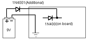
 1     MC68HC705C8 microcontroller          pre-programmed
 1     MAX232 line level converter          or ICL232
 1     SSI202 DTMF decoder
 1     LM358N dual op amp                   audio processing
 1     4066 analog switch IC                audio repeat
 1     LM7805 voltage regulator 5v          or LM78M05
 1     2N2222 NPN transistor                or PN2222
 1     1N4001 rectifier diode               polarity protection
 1     1N914 signal diode                   or 1N4148
 1     4 MHZ ceramic resonator              6805 oscillator
 1     3.579545 MHZ color burst crystal     DTMF decoder oscillator
 1     40 PIN dip socket                    for 6805
 1     26 PIN  box header rt angle pcb      data port
 1     18 PIN DIP socket                    for SSI202
 1     16 PIN DIP socket                    for MAX232
 1     14 PIN DIP socket                    for 4066 analog switch
 1     8  PIN DIP socket                    for LM358 op amp
 1     9 PIN D  female rt angle pcb         serial interface
 1     5 PIN DIN  female rt angle pcb       radio interface
 1     1/8 FEMALE audio jack rt angle pcb   secondary audio input
 1     DC POWER JACK  coaxial rt pcb        power input
 2     5 K TRIMMER pot                      audio and repeat levels
 1     SPDT TINI TOGGLE  rt angle pcb       power switch
 4     10 mf  electrolytic cap
 1     4.7 mf electrolytic cap
 3     .22 mf capacitor                     (224)
 3     0.1 mf  capacitor                    (104)
 1     2200 pf capacitor                    (222)
 2     0.01 mf capacitor                    (103)
 1     0.001 mf capacitor                   (102)
 3     1k  resistor                         (brown-black-red)
 1     1.3k resistor                        (brown-orange-red)
 1     2.2k resistor                        (red-red-red)
 1     3.9k resistor                        (orange-white-red)
 1     4.7k resistor                        (yellow-purple-red)
12     10k resistor                         (brown-black-orange)
 1     12k resistor                         (brown-red-orange)
 1     47k resistor                         (yellow-purple-orange)
 1     100k resistor                        (brown-black-yellow)
 2     1m resistor                          (brown-black-green)
 6     2 PIN jumper shunts
 1     1 x 2 jumper post                    jumper J8-E
 1     1 x 3 jumper post                    jumper J5
 1     1 x 5 jumper post                    extra
 1     2 x 4 jumper post                    jumper J8-A thru J8-D
 1     LED red                              power on indicator
 1     PRINTED CIRCUIT BOARD                the pretty flat green thing with holes
 1     4-40 x 1/4 W/WASHER & NUT            7805 hardware