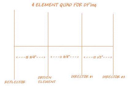
These are the skeletal plans for a 4 element quad used in direction finding.
The values that you see on the picture above represent the distance between each of the elements. The antenna
that I built is made of Schedule 40 PVC pipe. I used 1/2" for the framework and 3/4" for the mast. If you have ever
used PVC before you know that there is air space in between two pieces that are joined(ie; using a "T" coupler
to join 2 pieces of pipe). Therefore when you have to measure the distance of the length of pipe to use in order to
get the spacing of the elements correct, you need to allow for the space in between. For simplicity sake, I have calculated
the values for you. After you have the whole thing assembled, you must find the balance point. That is where you will attach the
mast section. Don't forget to compensate for the air space in the "T" coupler when you cut the boom. This is
very important. If you don't calculate this right, the spacing between the Driven Element and the first Director will
be off, hence the lobe will not be right giving inaccurate bearings.
The mast can be made of 3/4" PVC schedule 40 or what I found works better is a piece of aluminum mast.
This is OK since you are not transmitting with this antenna, so SWR is not a concern. If you plan to also transmit,
then you should not use the aluminum all the way to the boom. Make the last foot or so PVC. You also need to
use a Gamma Match to keep the SWR low.
The 1" diameter fits inside a piece of 3/4" "T" coupler just right with 1 wrap of friction tape or equivilant. Drive a
self tapping sheet metal screw through the coupler to secure it firmly. That about does it. There are many ways to
build this antenna. If you find a better way or feel more comfortable doing differently, by all means do so. The
most important factor here is the measurements of each element and the spacing. Deviate from that and you
may be searching for your hidden transmitter in another state. Good luck building it and if you have any
questions or comments, send me a note. Happy hunting!!!
These values might be different depending on the way you decide to suspend the elements on the boom.
The elements themselves are made of bare copper wire. I used 6 gauge wire. This is pretty thick stuff so it takes
a bit of work to straighten it out. You can use a thinner gauge wire, but it will become more susceptible to bending
when you are driving around. Just what you need to be doing in the middle of a "T" hunt; reshaping your antenna.
What I did was to make each element in 2 pieces. Then I soldered the pieces when I fit them on the PVC. To secure
the elements to each respective boom, I used a solderless eyelet. Bend them in a 90 degree fashion and solder
them to the element. One on each side; again depending on your design. The driven element needs to be
separated where ever the feed point is. I got creative and added 2 feed points. One for horizontal polarization and
one for vertical polarization. I used a PL259 on each for a quick changover if need be. The feed point that is not
in use, I shorted out with a piece of wire simply wrapped around the PL259.
Heres a picture of the finished product!!
Back to Stuff To Build Page