RF STEP ATTENUATOR


The schematic diagram of the step attenuator is designed for a nominal impedance of 52 ohms. Resistance values are in ohms. Resistors are 1/4 watt, carbon composition types, 5% tolerance. You must drill a hole through each partition wall to route bus wire. Keep all leads as short as possible. The attenuator is bilateral which means the input and the output ends may be reversed if you would like. Shielding partitions between sections is necessary to reduce signal leakage..From ARRL Antenna Book 1994 p27-37

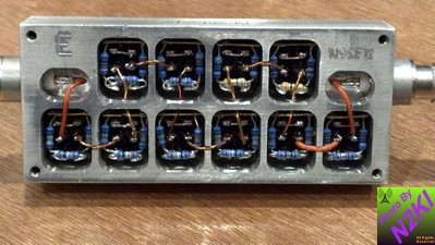
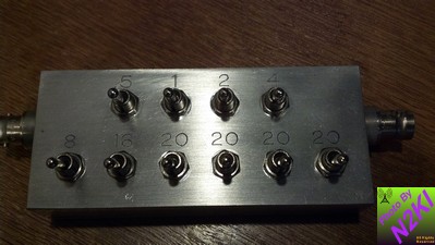
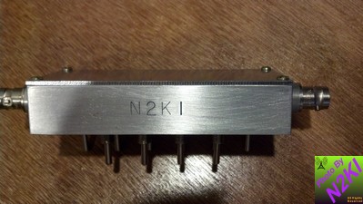
Here is another step attenuator.  It is the same concept as above, however the project box is honed from a solid block of aluminum creating excellent pi network isolation for proper attenuation with little to zero chance of "cross-talk" or bleed over.  You can purchase this kit from Pete Ostapchuk N9SFX.  He fabricates two kits; a 10 position and a six position.   The QST article is in the May 1998 edition.  You can download the article here.  Pete will also put your call sign on it for a more personal touch.


Back to Stuff To Build Page