|
|
|
APRS DigiTraker
With the success of the Mint Idea APRS Tracker, which has performed flawlessly over the last year, it was inevitable a second generation Automated Position Reporting System tracker would become both advantageous and a necessity. A few factors contributed to the desire to make it a reality:
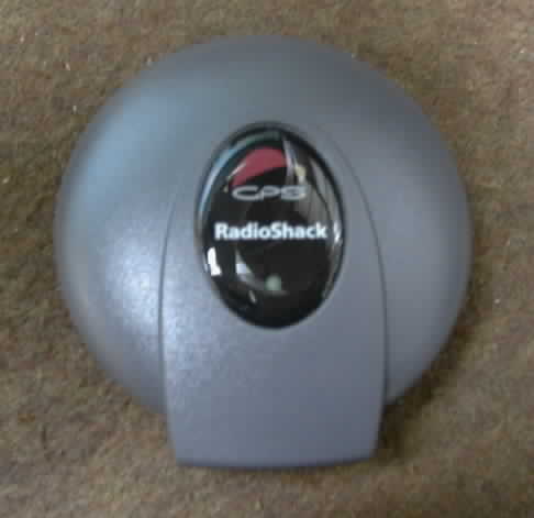
Major Component Overview Several months ago Radio
Shack® discontinued the DigiTraveler GPS series. Two models were available, 20-1601 for
use with a handheld PDA computer and 20-1602 for use with a notebook computer
serial port. The notebook
The differences between the two models are in the GPS to computer interface cables supplied and the mapping software. The notebook version includes a single interface cable terminated in a DB-9 serial port connector and DeLorme Street Atlas 2003 mapping software. The PDA version includes 4 cables terminated in connectors for popular PDA and includes Xmap Handheld Street Atlas USA mapping software. Either model can be used for our APRS tracker application, since none of the supplied cables or software are required. The GPS receiver module itself is exactly the same in each model package. I have read many descriptions of how GPS technology works. But none are as basic, yet complete, as the description of how GPS works from our friends at Radio Shack. I highly recommend that you review it to become familiar with the basic concepts described on their informative web page: A Guide to the Global Positioning System (GPS). If you are left still wanting more information, visit the University of Colorado website for the most comprehensive collection of information on The Global Positioning System available on the Internet. The heart of the DigiTraveler is the Sony GXB2000 16-channel GPS Receiver module. The GXB2000 is a small and lightweight device, and it includes all the functions required for GPS except for the antenna. The GXB2000 can support various kinds of portable applications as well as the car navigation system. Features
Recommended Operating Conditions
TinyTrak3, from
Byonics, is a GPS
position encoder which, when connected to a GPS and a radio transceiver, will
transmit its location at an adjustable rate. TinyTrak3 is a construction project
In January of 2003, Byon Garrabrant, N6BG, announced the then soon-to-be released TinyTrak3 and solicited suggestions for features and enhancements not found in the TinyTrak-II. I was fortunate to participate in the final beta test program for the TinyTrak3 and gained firsthand experience with its capabilities. Many of the features suggested or desired by the beta testers and the community of existing TinyTrak users were implemented in the final release. TinyTrak3 adds the following features to the previous TinyTrak-II:
TinyTrak3 also has the following features from the TinyTrak-II:
The initial goal and the driving force behind this project was the desire to integrate the assembled TinyTrak3 circuit board into the Radio Shack DigiTraveler GPS case. What I found is that the Radio Shack DigiTraveler GPS and the Byonic's TinyTrak3 make a perfect marriage. With a little ingenuity and a lot of patience the final result is the DigiTraker APRS tracker described here.
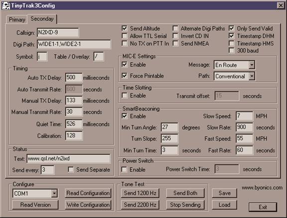
Building and Configuring the TinyTrak3 Assembly of the TinyTrak3 is straightforward thanks to a well written set of instructions and pictures. They provide step-by-step guidance as well as informative descriptions of component functionality in the overall design. You can download and review the TinyTrak3 manual in PDF format from Byonics before deciding to purchase the kit. The supplied components and newly designed dual-sided printed circuit board are of high quality. I would not recommend the TinyTrak3 as a 'first kit' for the neophyte builder. Parts placement is compact and demands good soldering skills typical of dual-sided printed circuit board projects. Aside from that, you will find construction enjoyable and trouble free. Jerry Karlovich, KD5OM, has developed a detailed PowerPoint presentation on assembling the TinyTrak3. I highly recommend that you review it before undertaking construction if you are not an experienced electronics kit builder. However, should the need arise, technical support can be found on a YAHOO! Group dedicated exclusively to the series of TinyTrak products. There you will find advice and instruction from an experienced community of TinyTrak users and often from TinyTrak creator Byon Garrabrant himself. Testing, configuring and troubleshooting the completed TinyTrak3 is covered in full detail in the manual. Configuring user selectable settings is accomplished using the supplied TinyTrak3config.exe program tool shown below. It allows total programming flexibility for various modes of operation. Primary and Secondary configuration modes permit programming two complete sets of operating parameters which can be easily selected through a hardware jumper on the circuit board. Both configurations can be written to a file on the PC for easy loading and modification at a later time. This feature offers significant improvement over the programming tool supplied with the TinyTrak-II. Typical configurations for my intended use are displayed below.
The configuration above shows my normal mode of operation. SmartBeaconing is enabled. In this mode the beacon rate is determined by the speed and direction of my vehicle. The faster I travel, and therefore the more distance traveled per unit of time, the more frequent the beacon transmissions announcing my location. When stationary or at speeds below 10-MPH the beacon rate is less often. As programmed above, my beacon transmission rate varies between once every 15-minutes (900-seconds) when stationary, to a maximum of once every minute when traveling over 55-MPH. See the complete description of the SmartBeaconing algorithm in the TinyTrak3 instruction manual.
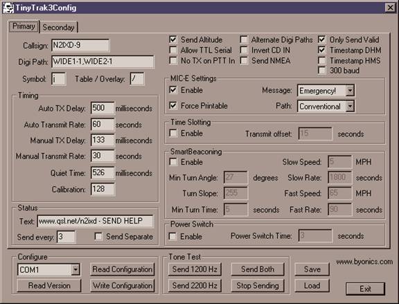
In the configuration above SmartBeaconing is turned off and the beacon transmission is at a fixed rate (every 60-seconds) determined by the Auto Transmit Rate parameter. Notice the MIC-E Message selected and the Status Beacon Text. This configuration has one intended purpose -- to announce an emergency and request help. It is a configuration that I hope never has to be enabled, but is in place should the need arise. It is activated by easily removing a two-pin jumper on the TinyTrak3 circuit board. Recommended TinyTrak3 Settings (See the TinyTrak3 manual for a detailed description)
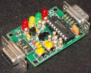
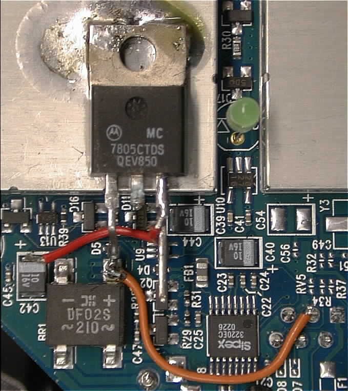
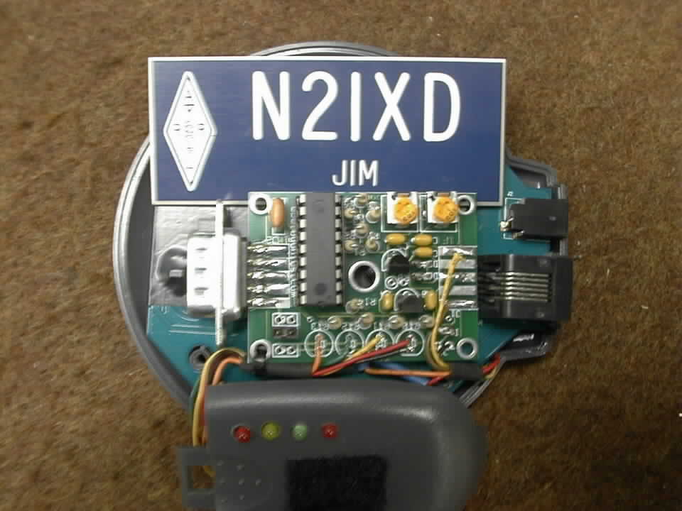
Modifying the DigiTraveler GPS To accomplish the goal of integrating the TinyTrak3 circuit board into the GPS module, several modifications to the Radio Shack DigiTraveler GPS were required. The GPS has two connectors, a coaxial style power connector for 6-volts DC and a 6-pin RJ style connector for connection to external PC/PDA devices. Each of the supplied interface cables consists of an RJ male connector and either a DB-9 or proprietary PDA connector. In each case only three data lines are used: serial IN (pin-2), serial OUT (pin-3) and Ground (pin-5). This can be further reduced to two data lines, serial IN (pin-2) and Ground (pin-5) with the first modification. But before making changes to the GPS circuit board you may want to first verify that your GPS is functional. The easiest way to do that is to install 3 AAA batteries into it and connect it to a computer serial port. If you purchased model 20-1601, DigiTraveler for PDA, you will need to modify one of the supplied cables. Do this by installing a DB-9 connector in place of the PDA connector. Then use Windows Hyperterminal configured for serial port COM1 (4800,8,N,1) or a dedicated GPS monitor program like VisualGPS to verify that it is spitting out a data stream of NMEA sentences. No actual data or communications takes place from the PC/PDA to the GPS on pin-3. Serial OUT (pin-3) is used for one purpose only -- voltage sense to turn the GPS on. In other words, the GPS is in standby mode when there is no voltage (data) on pin-3. This allows the GPS to power-on or power-off (standby) depending on whether it is connected to an active PC serial port or PDA port, thus conserving power and extending battery life. This eliminates the need for a GPS On/Off switch and eliminates the need, in our application, for Serial Out (pin-3). Instead we will use pin-3 to provide operating power for the GPS and the integrated TinyTrak circuit board. The GPS requires between +3.0V and +5.5V to operate. This is normally supplied by the 3 AAA batteries installed in the battery compartment of the GPS module. For our purposes the battery compartment is removed to make room for the TinyTrak3 circuit board, so another means of powering the GPS and the integrated TinyTrak3 is required. The 3.9 mm outside and 1.7 mm inside diameter coaxial power connector on the DigiTraveler is marked 6-volts maximum. For our purposes it is more desirous to supply +12V to +13.8V directly from the vehicle power system thereby eliminating the need for an external voltage reducing adapter. The coaxial power connector feeds
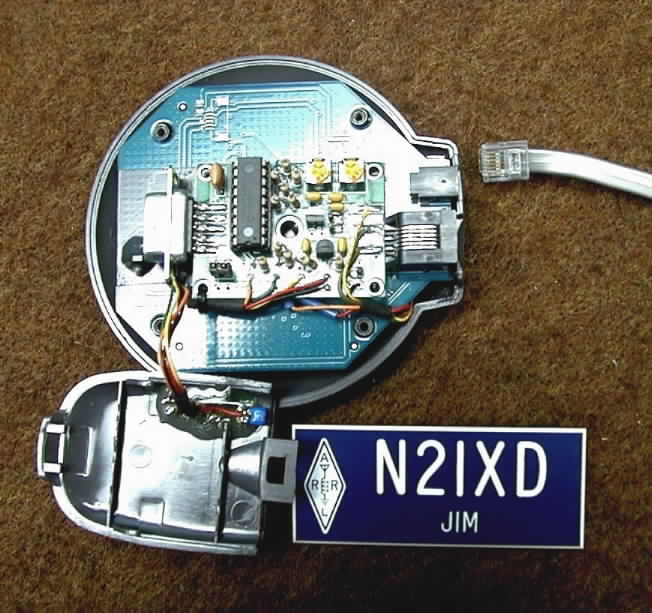
a bridge rectifier (identified as BR1, lower left of picture) on the GPS circuit board. The purpose of this bridge is
to convert either +V or -V center pin input from the coaxial connector to a
constant polarity output. In essence
it provides effective reverse polarity protection. The next modification
requires mounting an LM-7805 three-pin voltage regulator IC on the metal shield
located near the bridge. This is done by heating both the GPS metal shield and
the regulator metal tab and then flowing solder around the The remainder of the steps demand precision soldering skills. I highly recommend a low power (25-Watt) pencil-point tip soldering iron whenever working with surface mount components. First, carefully lift the bridge rectifier output pin marked "+" from the GPS circuit board. This is easily accomplished by inserting a small tool like a jeweler's screwdriver between the side body of bridge rectifier BR1 and the "+" pin of bridge rectifier BR1. Heat the solder pad where the "+" pin is soldered to the PC board and gently pry the pin away from the solder pad with the jeweler's screwdriver. Use enough heat to loosen the pin before applying prying pressure. Avoid too much force when prying to prevent damage to BR1. Solder the separated "+" pin to the input (left) pin of the LM-7805 voltage regulator IC. Connect the output (right) pin of the IC to the solder trace on the GPS circuit board where you removed bridge BR1 "+" pin from. An alternate location to connect the LM-7805 IC output pin to is the "+" side of capacitor C42. It provides a better solder point for this connection. I used the short red wire in the picture to complete this step. The LM-7805 middle pin (ground) is internally connected to the metal tab and is left unconnected here. Finally, attach a short piece of wire between the junction of the LM-7805 input pin and the BR1 "+" pin, and the solder pad at pin-3 of the 6-pin RJ connector. See the orange wire in the picture. What we have accomplished here is the ability to power the GPS by supplying ±6V to ±35V through the original DigiTraveler coaxial power connector or by supplying +12V from the vehicle supply sent up the six-wire cable to RJ connector pin-3. Regardless of the source of power the GPS sees a constant +5V operating voltage provided by the LM-7805 voltage regulator IC. We now have pins 1, 4 and 6 available for interfacing the radio transceiver with the integrated TinyTrak circuit board. A suitable 6-wire cable terminated with the appropriate RJ connector on both ends was obtained from a recent Hamfest. They are commonly used in modern multi-line business telephone systems and are easily obtained from other sources. I cut the 6-foot long cable in half resulting in two cables terminated in a 6-pin RJ connector and wire leads for interfacing. The remaining steps are
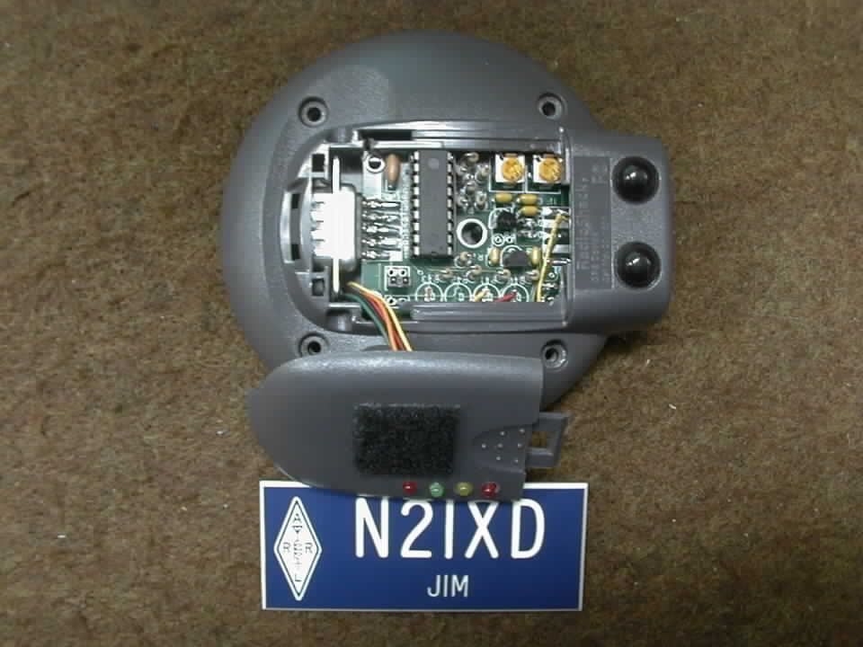
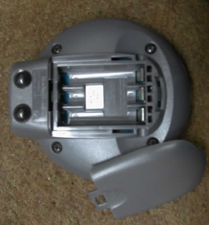
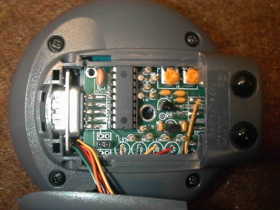
relatively straightforward. The battery compartment of the DigiTraveler GPS must
be removed to make room for the TinyTrak3 circuit board. The area occupied
by the battery compartment is the only available space where access to the board
can be maintained for adjustments to R6 and R9 trimpot resistors and the jumper
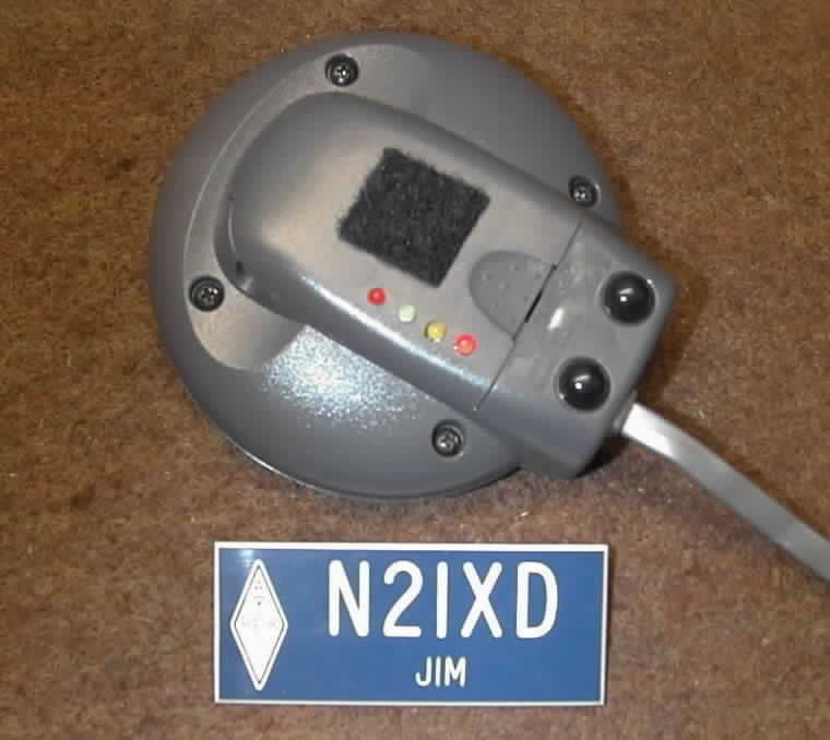
for changing Primary and Secondary operating You can elect to mount the
TinyTrak3 status LEDs on the battery compartment cover as shown or mount them in
their original locations on the circuit board. Final requirements are to route
Push-to-Talk, Transmit Audio and
Receive Audio (carrier detect) lines from the transceiver through the 6-wire
cable to unused pins 1, 4, and 6 and then to the appropriate points on the
TinyTrak3 circuit board solder pads where J1 would
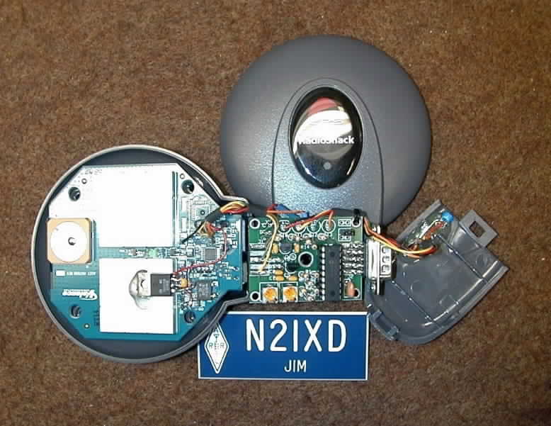
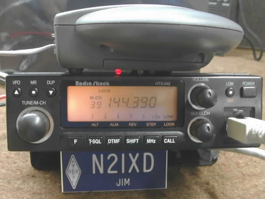
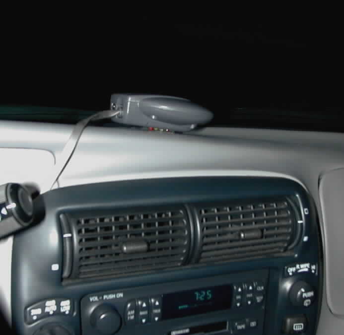
DigiTraveler + TinyTrak3 = APRS DigiTraker There you have it. The
perfect marriage of GPS and packet data encoder in a compact, lightweight,
single cable interface package. I terminated the opposite end of the RJ
interface cable with a DB-9 female connector wired in standard Kantronics TNC
fashion. This allows easy switching of radio transceivers for flexible use.
Each
of my radios has a pre-wired Kantronics style cable that connects to either the
radio I mentioned earlier the
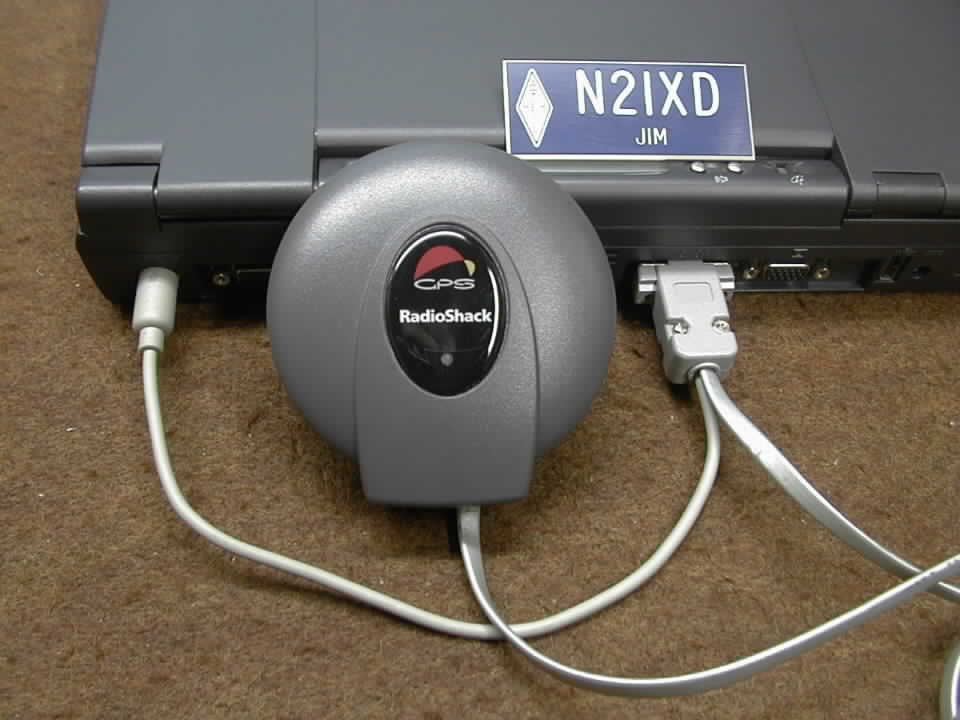
importance of maintaining GPS data out (Serial IN) on pin-2 of the RJ connector.
Doing so allows easy connection to a PC serial port using a second interface
cable. This will allow the Digitraveler GPS data to be used directly with
popular mapping software programs like DeLorme Street
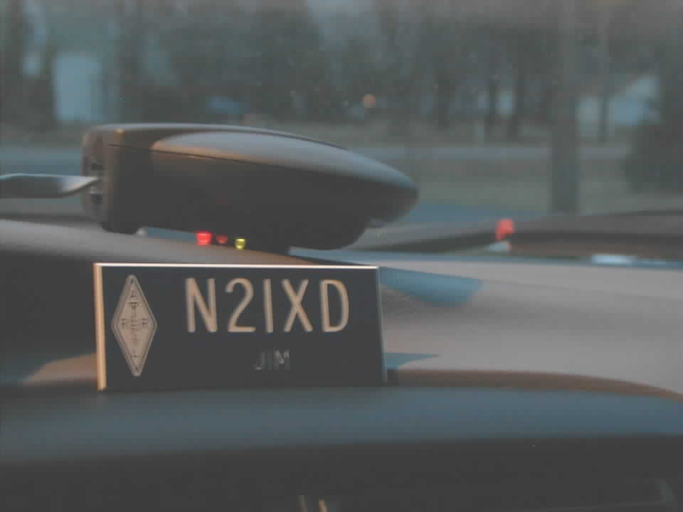
DigiTraker Pictures
ã2004,
N2IXD
Notice:
This work is protected by U.S. and International Copyright Laws and is the
Intellectual Property of its author. Unauthorized use of this resource for
activities other than those permitted by applicable acts, codes and legislation
is strictly prohibited.
| ||||||||||||||||||||||||||||||||||||||||||||||||||||||||||||||||||||||||||||||||||||||||||||||||||||||||||||||||||||||||||||||||||||||||||||||||||||||||||||||||||||||||||||||||||||||||||||||||||||||||||||||||||||||||||||||