The predicted coverage for the system presented on this page is for reference only. It has been created using a combination of technical facts and known system performance.
Below we will present two types of coverage area plots that represent the predicated normal coverage area that a mobile (35 watt average) station using the typical 5/8 wave UHF mobile antenna can expect to experience using the repeater system when in the clear. We will also provide predicted coverage area for a hand held (5 watt) user with a 1/4 wave rubber duckie antenna.
The plots depicted below will be of two types, those that are created using Digital Elevation data taking into account antenna height above average terrain of the repeater system antenna and those that using Tiger data for mapping that take into account the system EIRP and antenna height above Ground and Sea Level for distance but not terrain characteristics.
The image below shows the location of the N2CKH/R 70 centimeter repeater system located in Lakewood, New Jersey area as georeferenced on a map created using Sight It!™ LOS Calcuator™ terrain analysis software by N2CKH.
This map is created by imaging 1 degree by 1 degree Digital Elevation data distributed on the Internet free by the U.S. Geological Survey (USGS), it is called Digital Elevation Model (DEM) data, and is provided in 1 degree, 30 minute, 15 minute and 7.5 minute coverage areas, most amateurs are familiar with 7.5 minute topographical maps for determining their exact coordinates and elevations.

In the image above, what we are looking at is an image created to display in colors for each elevation bin set in the software, as can be seen on the elevation bin color/range box in the lower left, with Black as sea level and Dark Blue 1 to 17 meters in elevation, also we have turned on the Cities overlay layer for a point of reference, we could also have or instead of Cities turned on political boundaries and shown County and or State boundary outlines.
We also have the Sun shading of the elevation data so that you can now see the hills and ridges of the terrain, now go back and look at the 360 degree coverage fans in the image below and you can see really see where the blockages are to the LOS from the repeater site to the north.
The image below shows the coverage of 447.925 taking into account the height of the antenna at the 6m repeater site out to a 25 mile radius in a 360 degree fan pattern.
This coverage does NOT take into account foliage, man made obstructions or even the antenna pattern of the repeater site antenna.
As you can see the plot depicts the mobile coverage pretty darn close to what is haas turned out to be in the real world. Where you see the PURPLE is Line-Of-Sight to the repeater antenna for the average terrain, thus is it is also the basic mobil coverage of the repeater when using at least 20 watts and even better with 50 watts.
This does NOT mean that outside the PURPLE area that you can not get into the system. I have worked the machine well beyond, but only when in the clear and at higher road elevations. The system exists to provide over lapping coverage with the AERIALS Inc. 443 repeater located in the township of Ocean where 443 has holes in coverage to the west and south.
Due to the ridges to the Northwest, North and especially the Holmdel hills to the North East really block the line of sight and the signal. However, the 443 system in those areas and beyond is excellent.

Also, do to the nature of the 1 degree DEMs from the USGS and the fact that Sight It!™ has been written to combine DEMs, you do not see the actual full 360 degree sweep as the physical location of the repeater is in the lower right quadrangle of the DEM thus the cricle goes off the coast line where land mass ends, in this case it doesn't matter for two reasons, no land and 443 is over that way.
The image below depicts the 15 mile (24km), 20 mile (32Km) and 30 mile (48km) radius coverage area for the transmitted signal of the repeater when mobile. You can hear and work the system solid in most places in the clear while mobile within the inner cirlce (15 miles).
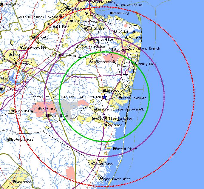
Within 5 miles of center HT performance is great when in the clear, it is still good beyond depending on location, but unless really high and in the clear you do not go past 10 miles with an HT.
Between the 15 mile and 20 mile circles the machine starts to get spotty in places, espcially North East, East and to the South. But is still excellent copy while mobile in most places when in the clear to the South, North and West. Getting back into the system with the typical 5/8 wave mobile antenna is subject to many variables of terrian, foilege and man made structures. The terrain to the North East and East is very high and to the South drops off real fast.
Between the 20 and 30 miles radius and beyond hearing the system while mobile is subject to mobile location. Basically the range of the repeater for mobile operations is limited to about 30 miles. Base stations will easily work the system from 30 miles and more with good antenna installations unless they have blockage bewteen them and the repeater site.
When traveling about mobile or using hand held radios switching between 443 and 447.925 will allow for continuous coverage over most all of Ocean and Monmouth counties. Visit the AERIALS web site for the 443 coverage plots.
For information on my commercial amateur radio products please click here to send e-mail or visit the main website.
