TOWER PICTURES 2
|
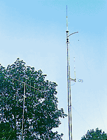
All 11 sections are up, and a few accessories are already
installed. The top plate is at 110'. The mast, which is
6061-T6 aluminum, 2" dia. by 0.25" wall,
extends 9' above the top plate. The lightning rod is
actually a copper-clad ground rod, mounted up-side down
(with the point up), and it extends another 7 feet to
reach 126' overall. This rod should intercept any
lightning strikes and won't explode into a thousand
pieces like a fiberglass vertical antenna!
|
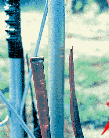
Here's how I started bonding the radials from the
lightning ground system to the tower itself. I first
cleaned each leg thoroughly using isopropyl alcohol and a
Scotchbrite pad. Note that there are two flexible risers
for each of the three legs. Next, I squeezed the two
sections of tubing with pliers to start the flattening
process. I also turned over the ends and crimped them
shut with vise-grips.
|
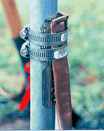
When copper touches a galvanized part outdoors, it forms
a nifty corrosion cell via galvanic action. To prevent
this, I am using pieces of thin, stainless steel foil as
an intermediate layer. You can also see some antioxidant
paste squishing out from behind the foil at the top and
between the foil and tubing at the bottom (NoAlox). All
stainless hose clamps will provide the necessary clamping
action..
|
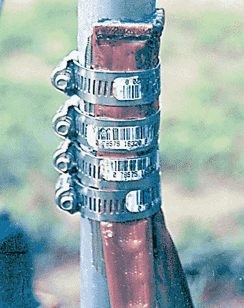
To form a perfect contact patch, I lightly peened the
edges of the flattened tubing toward the tower, using a
hammer. Then I drew up the slack with each hose clamp. I
alternated between peening and tightening until I was
sure each tube had a very large contact patch for minimum
impedance. To finish, I wrapped each joint securely with
UV resistant electrical tape to seal in the antioxidant
paste and keep out rain from washing it out.
|
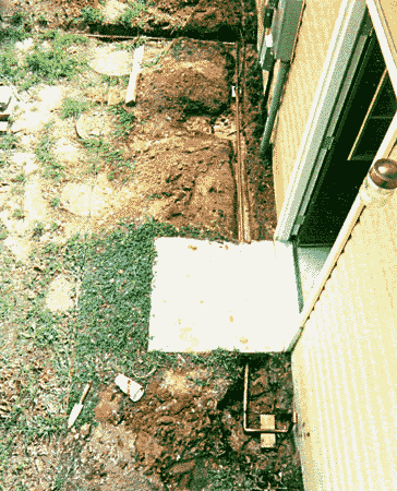
This view shows the rear of the garage where I extended
one of the tower grounding legs to tie into the service
ground. I excavated a little to find the service ground
rods and wire. I extended the 3/4" water pipe along
the foundation, parallel to the service ground, under the
pad by the door, and up to a stub. There are two
additional, 10' ground pipes in this line to beef up the
ground before the stub comes up.
|
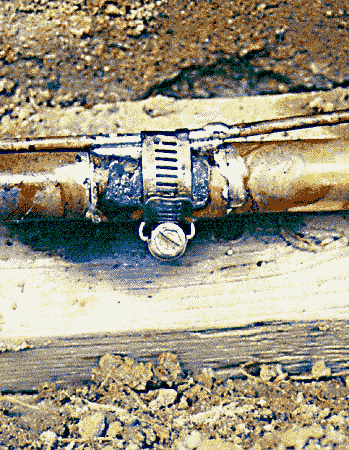
Here's a close-up of the tie-in with the service ground.
The hose clamp provides the mechanical bond, and the
solder makes the electrical bond. It may not look pretty,
but so what? It is now buried!
|
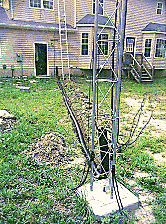
Here's the 40' trench that will carry all the cables
between the tower and shack. I am using 4" ABS pipe
and a shallow trench. The winters are mild here in VA, so
I won't have to worry about frost heaving.
The underground pipe sections are slotted to prevent
water buildup, and the sections that rise above the
ground are un-slotted to help keep rain out.
|
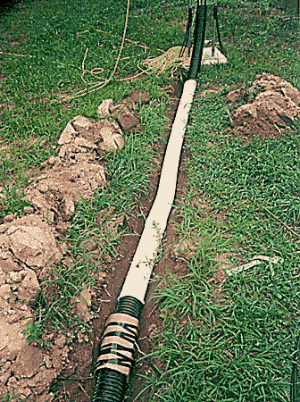
Here, I am using an improvised, cardboard shuttle tube to
put the dirt 'socks' over the ABS pipe. These will keep
dirt and bugs out while allowing any water to drain out.
|
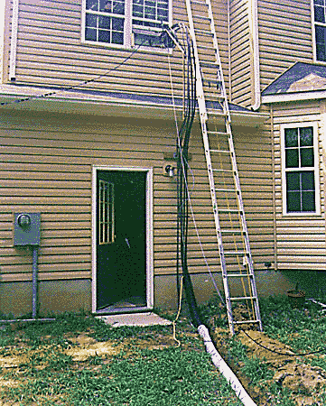
Next to the rear wall of the house, where the trench
ends, I extended the 3/4" copper pipe stub upward
toward the right-hand window in the 2nd story shack.
There are 8" long stubs every few feet on this riser
to which I tied the cables as they go up, adding support.
There is a homebrew, grounded entrance panel in the
window, bonded by the water pipe riser, where all cables
are terminated with bulkhead connectors (separate
project).
|
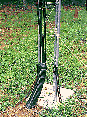
I cut holes in ABS pipe caps to fit accommodate all the
cables and sealed them with putty to keep rain from
running down into the pipe. This added a nice, finished
look to both ends.
|
On
to tower picture gallery 3
|
Good luck and
have fun with your tower project!
--...MARK_N1LO...--
|
since 12/21/99