Select IC or part for description and picture.
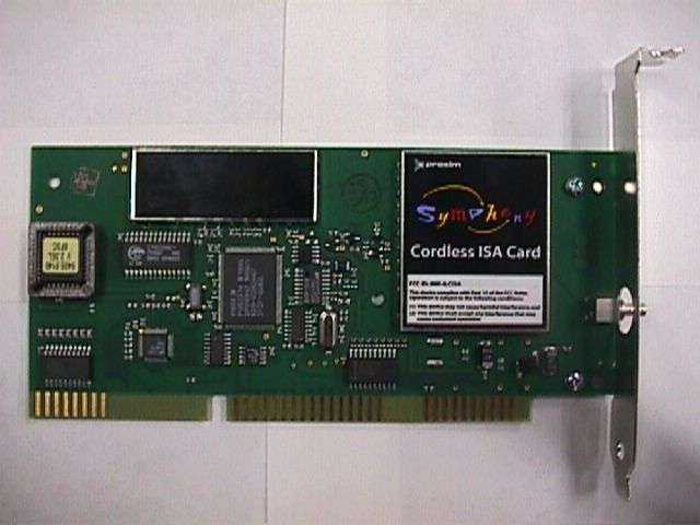
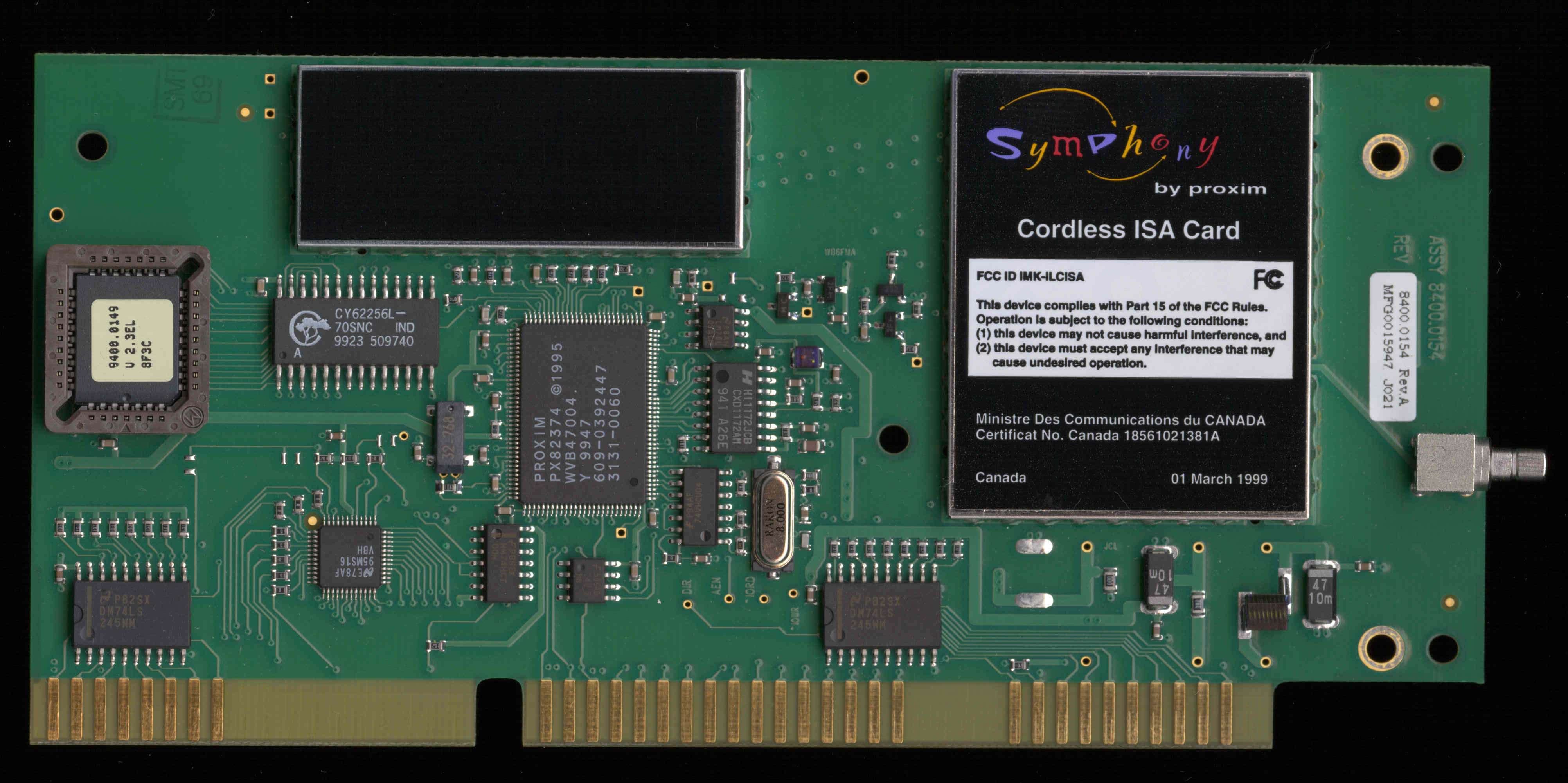
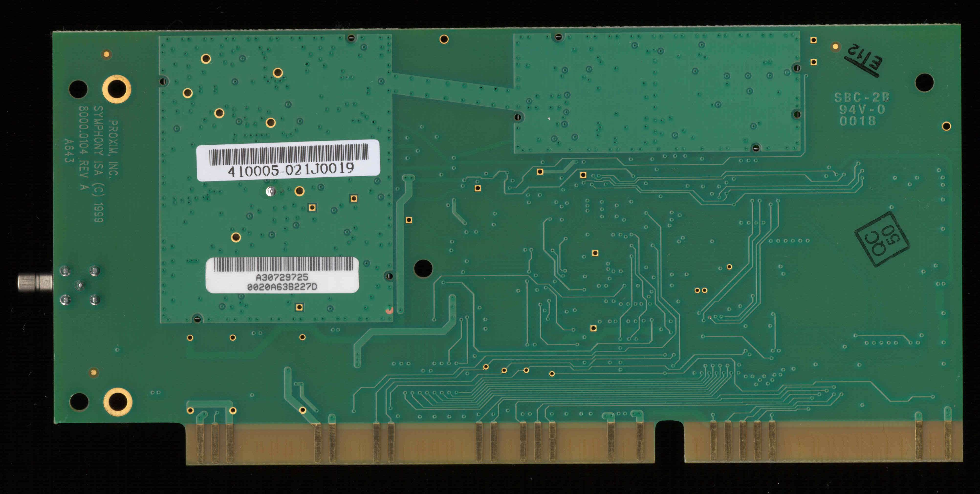
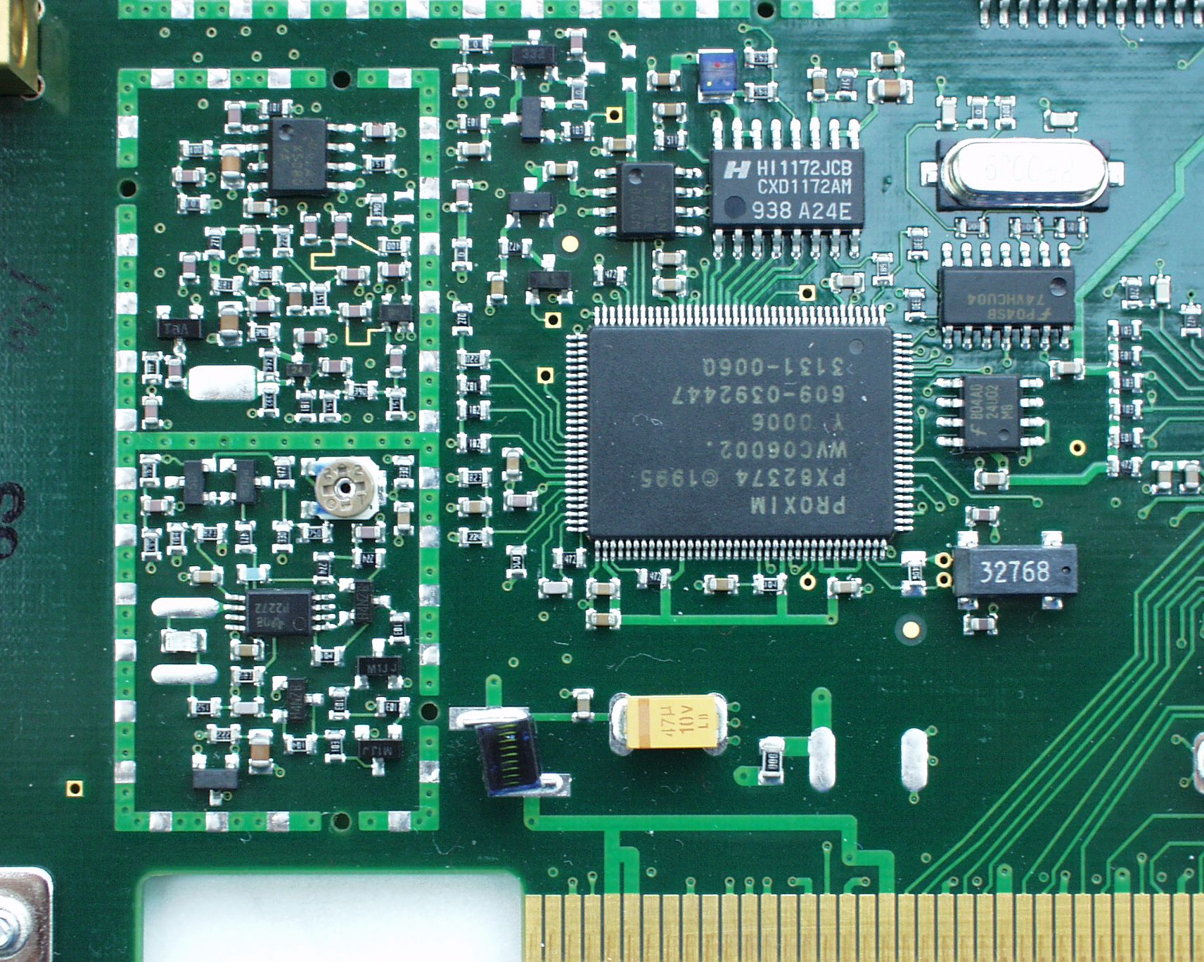
High resolution scans of the PCI Symphony overview, RF section and controller section.
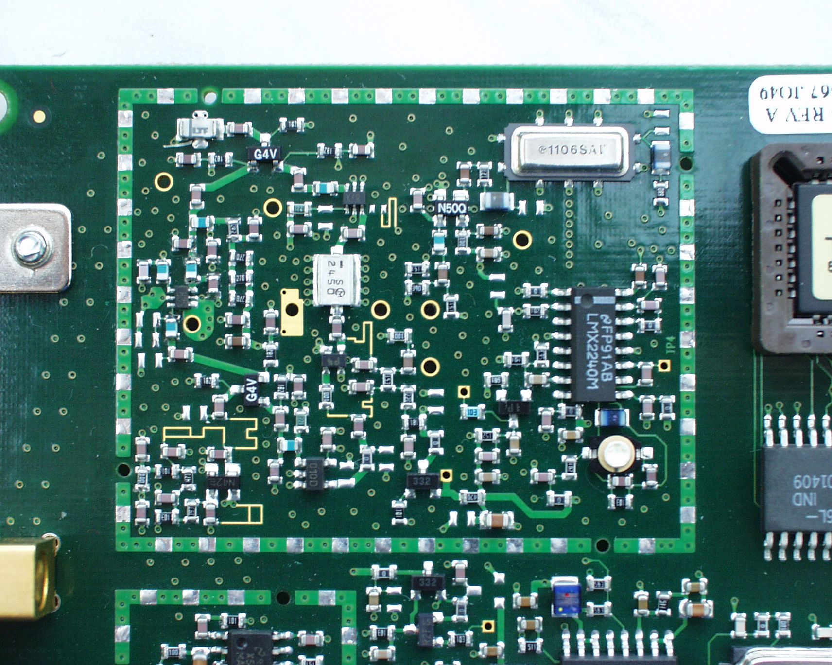
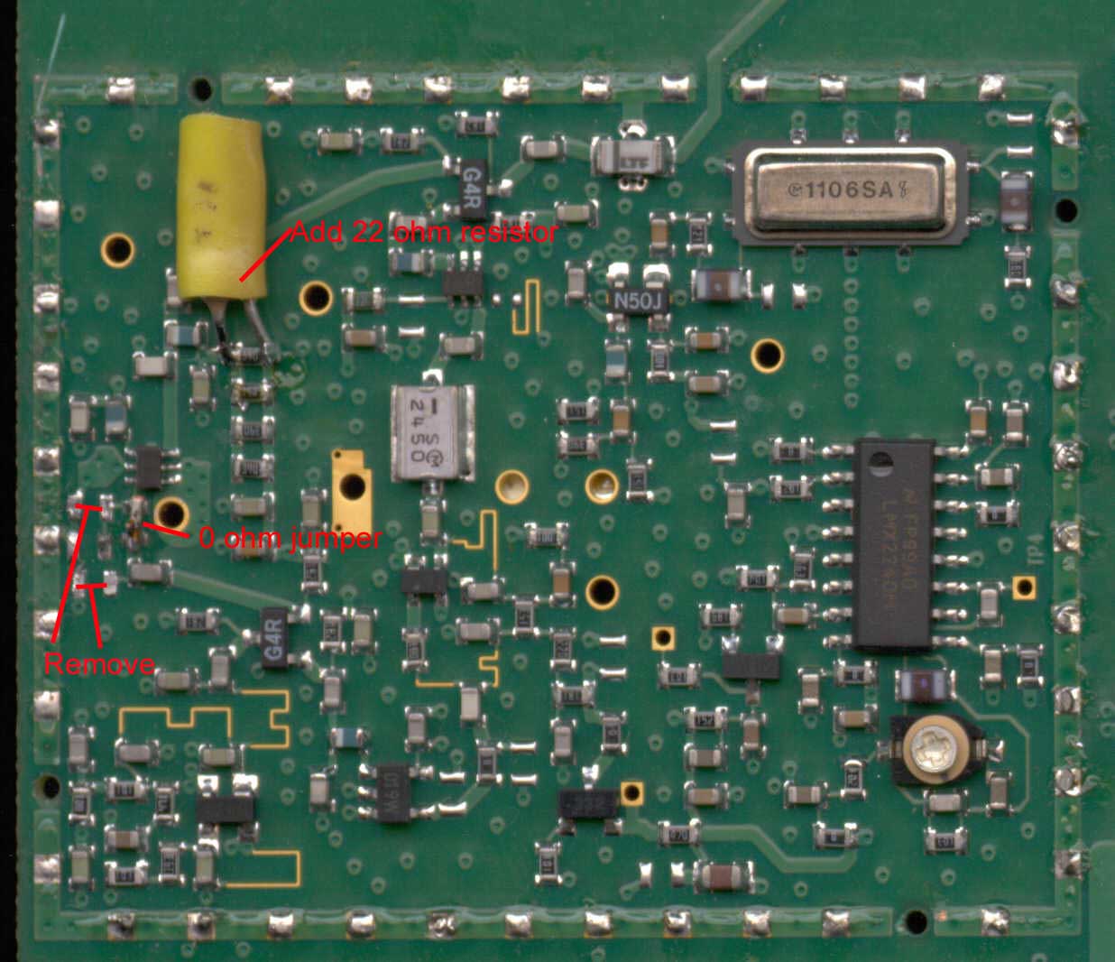
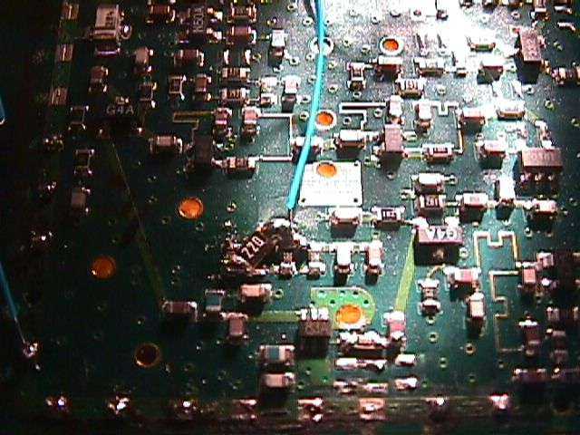
High resolution scans of a modified Symphony under the main RF shield.
High power (400 mW) modification for the Proxim Symphony wireless Ethernet bridge.
Additional Notes
This card is labeled "REV19"
There appear to be test points on the card marked:
DIR - direction control ??
AEN - address enable ??
IORD - I/O read ??
IOWR - I/O write ??
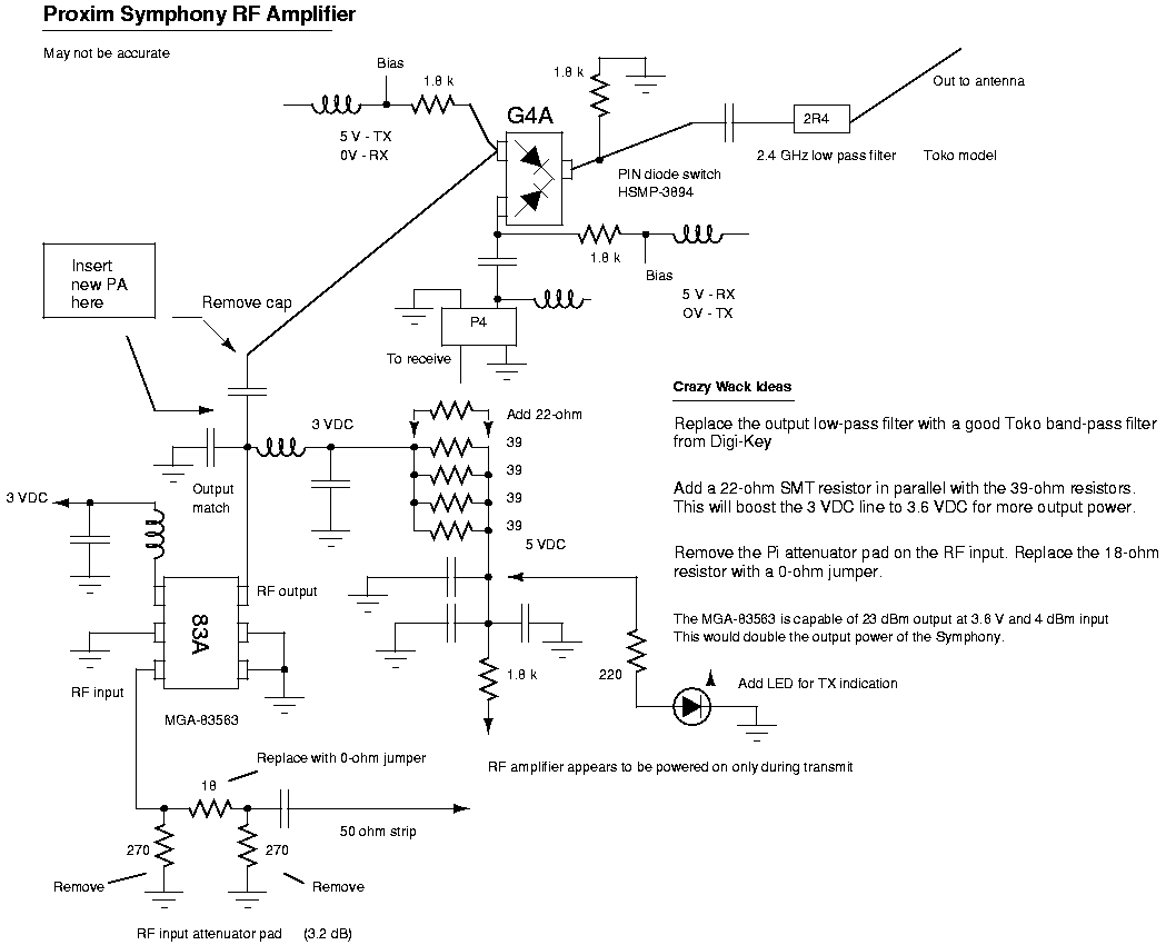
The RF power amplifier IC, a 6-pin IC marked with "83A", is an Agilent Technologies MGA-83563 running at 3 volts DC, dropped from 5 volts with a few resistors. It's possible to change out those resistors and run the IC at 3.6 - 3.9 volts to get more RF power output. The maximum DC voltage for this IC is 4 volts and the maximum RF power output is around +23 dBm (200 mW).
The best way to do this would be with another parallel resistor. Adding a 22 Ohm resistor in parallel with the four 39 Ohm resistors would bring the total resistance to around 6.8 Ohms. This should give you 3.6 VDC on the power pin. WTF?? Show your math...
	Vd = Dropping resistor
	V1 = Voltage on the power line
	V2 = Voltage you want V1 dropped to.
	I = Current draw

	Vd = (V1 - V2) / I

	Substituting the Symphony values:

	9.75 = (5 - 3) / I

	I = 2 / 9.75

	I = .205 amps

	Calculate the new value Vd:

	Vd = (5 - 3.6) / .205

	Vd = 6.8 Ohms

	Which is the value of four 39 Ohm resistors and one 22 Ohm in parallel.

	This can also be adapted to other wireless network cards.
You should also remove the Pi-style attenuator pad in the RF input. This also increases the RF power output a little. Just remove the two 270 Ohm SMT resistors going to ground and replace the series 18 Ohm resistor with a 0 Ohm jumper.
The PIN diode switch is an Agilent Technologies HSMP-3894.
The intermediate frequency (IF) receiver is based on the National LMX2240. Visit that site for datasheets and application notes.
Tap Points For Transmit/Receive
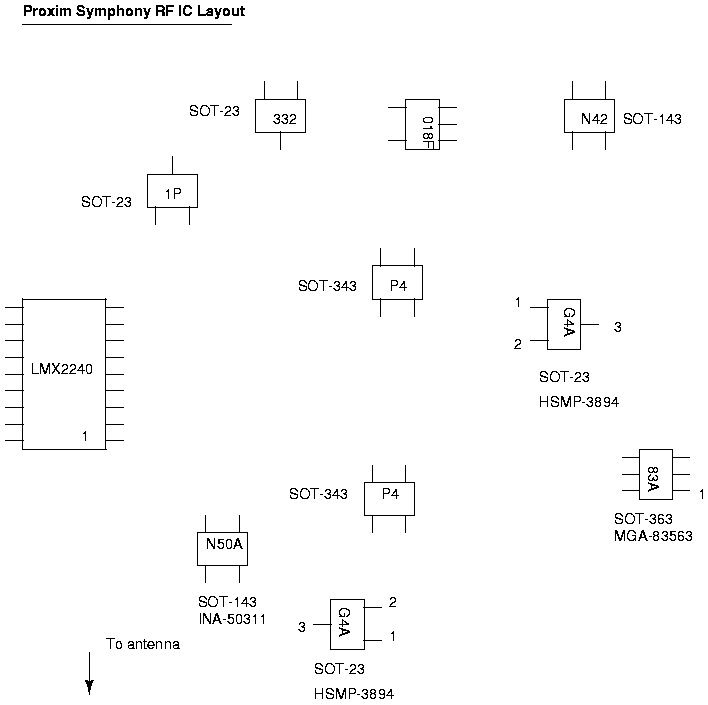
It's be possible to tap the PIN diode bias line to control an external amplifier. When viewing the pictures, locate the PIN diode switch, near the antenna output and labeled with "G4A", and tap before the small SMT bias resistor. This is a TTL (+5 - 0 volts) indicator of transmit/receive and can be extended to control an external power amplifier. Measuring RSSI output voltage is also possible by following the output of pin 2 on the LMX2240 and measuring the voltage on the little solder pad. Refer to the LMX2240 data sheet for more info.
- Partial schematic of RF amplifier section (30k PNG)
- RF IC layout (14k PNG)
- Symphony modification Shows the 22 Ohm parallel resistor and the 0 Ohm jumper (77k JPEG)
- Symphony modification Taping the RSSI on the LMX2240 (70k JPEG)
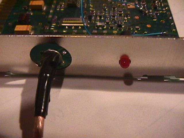
- My funky transmit LED (41k JPEG)
- Pictures of oscilloscope traces on the RSSI and PIN diode bias lines
Thank you for the message. However, I am unable to provide you the information you seek. Proxim is required to remain within FCC guidelines for emissions on our products, and amplifying the output would violate this. I understand that you have a radio license, however, we are not able to provide the information which goes outside the specifications that we are certified under. In the same vein, our board designs are proprietary and therefore we can not disclose the design details you seek.
We apologize for the inconvenience this may cause you. Proxim certainly wants to support its user base, however, we must remain in conformation with regulatory guidelines and reasonable business practices.