This section will list several projects which will allow you to build your own RF design test equipment. Microwave construction techniques and basic electronic skills will be required on some projects, but the tools you can make will equal what the so-called "professionals" use.
- Modified Wireless Tools
- RSSI Based Signal Meter
- Simple Analog Field Strength Meter
- Attenuator Pads
- Cable Reflection Tester
- 2.4 GHz Quarter-Wave Power Divider/Combiner
- Audio/Video Transmitter Link Test
- LED RF Signal Meter
- Spectrum Analyzer
- 2.4 GHz RF Power Meter / SWR Meter
- Return Loss Bridge
- Antenna Analyzer
- 3 GHz Prescaler
- Bias Tee
- Jammers
- Simple VHF Power Amplifier Design
- 10.000 MHz Precision Frequency Standard
- 2.4 GHz to 700 MHz Converter
- 2.45 GHz Bandpass Filter
- 2.4 GHz Antenna/Feedline Analyzer
- 20 dB / 150 Watt Attenuator
- RF Detector / RF Probe
- 2.4 GHz Receive Converter
- Miscellaneous Useful Circuits
- Homebrew Test Equipment / RF Design Links
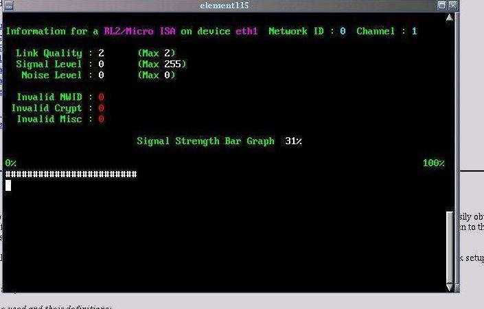
We modified the iwconfig command included with Jean Tourrilhes' Wireless Tools for Linux slightly to help with the wireless link setup and alignment. Here is what the original output of the command iwconfig eth1 would look like:
eth1    RL2/Micro ISA  NWID:0  Channel:1
        Link quality:2/2  Signal level:80/255  Noise level:0/0
        Rx invalid nwid:0  invalid crypt:0  invalid misc:0
Here is a screen shot of the modified version. It displays the same information, just with some lame ANSI colors and a bar graph for signal strength. I'm not sure if it's entirely accurate, so use at your own risk. You can pick this version up here. There is also a version for the 915 MHz WaveLANs.
It also includes the perl script pinger.pl, (screen shot) you can use this as a signal meter to help align the antennas in your network. It's just a wrapper around the ping command to display the millisecond output with an ANSI bar graph. It also has an option for using the 'say' command from the rsynth package to speak the ping millisecond value to you. That's useful for when you're hanging from a tower trying to align antennas.
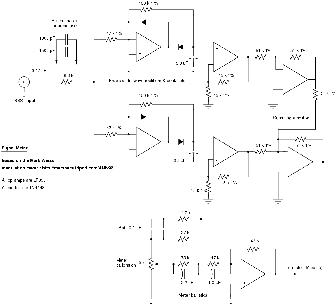
Another method of testing the received signal strength on a Symphony based wireless network is with a homebrew signal meter. The National LMX2240 Intermediate Frequency Receiver has a certain pin called "RSSI Out". RSSI stands for relative signal strength indicator and supplies a voltage output that is an indication of the received signal strength. On a weakly received signal the voltage output of the RSSI is small and on a strong signal it's large. Unfortunately, this output is only on during the receive portion and off during transmit. This makes the RSSI output look like a series of spikes. To average out these spikes you can use a very common piece of test equipment on any good technician's bench: a modulation meter. What? You say? Modulation meters convert received audio signals into a DC voltage indication of modulation, if you input the RSSI spikes into the meter (and readjust its ballistics) you will get a poor man's signal meter. The meter I use is based on the Mark Weiss modulation meter.
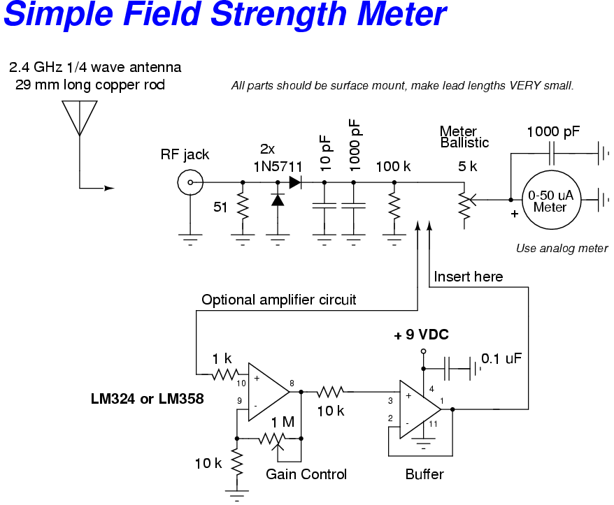
This is a simple field strength meter that can be used to verify that you antenna is in fact radiating energy. It's based on one from the ARRL UHF/Microwave Projects Manual, Volume 1 and can be used from 30 MHz to well over 2 GHz if properly constructed
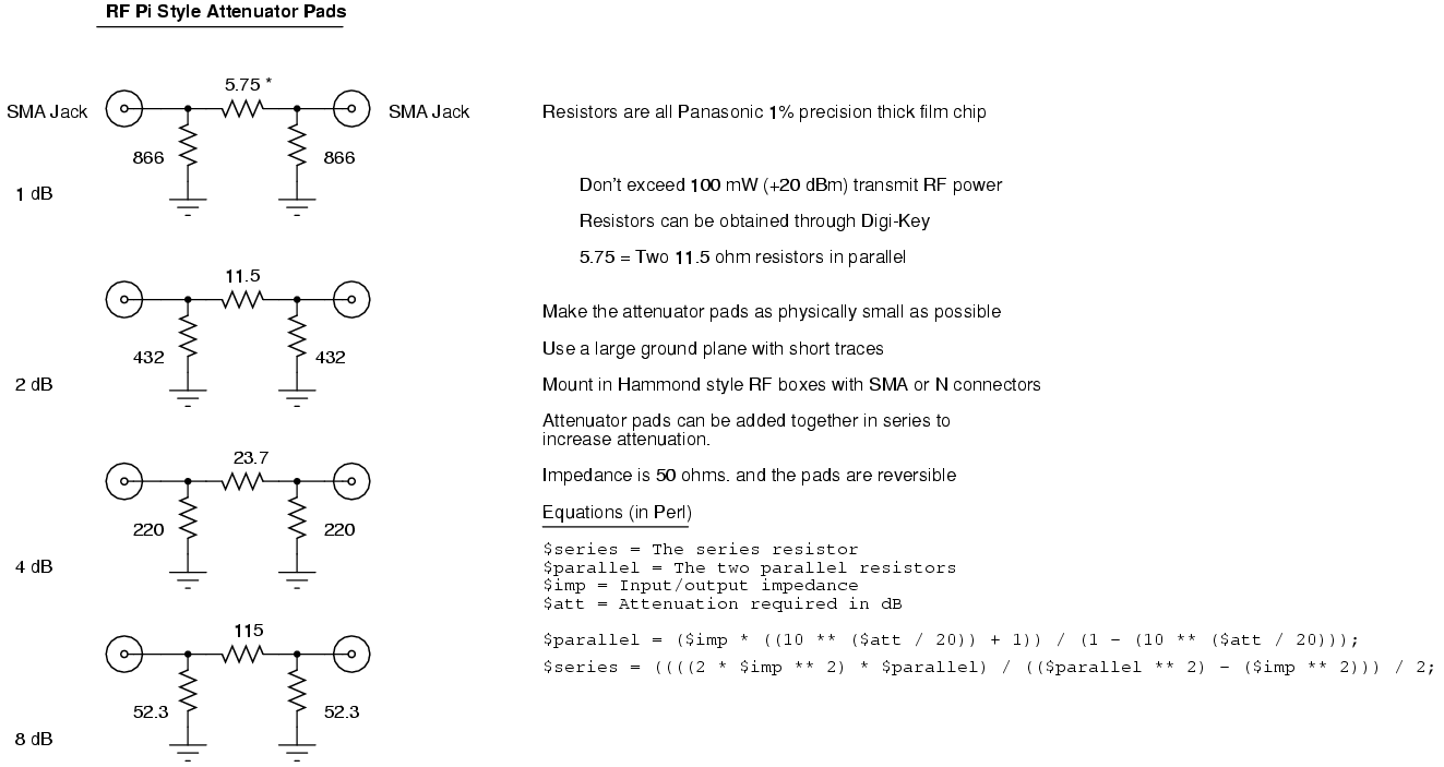
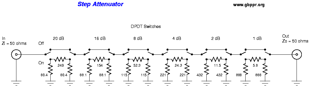
You can also make some attenuator pads to help simulate real life signal loss when testing your wireless network links. If you wish, you can order commercial inline attenuators from Mini-Circuits that will handle 2 Watts of power, DC - 18 GHz, and have built in SMA connectors for around $37 a piece. You may also combine attenuator pads to increase the overall attenuation. It's also possible to use a long length of high-loss cable, such as RG-174, as an attenuator.
Higher wattage resistors will handle higher RF power, though the frequency response will suffer due to parasitic reactances. Lower wattage resistors will handle higher power if applied in small durations (milliseconds), like which is commonly found in most wireless network applications.
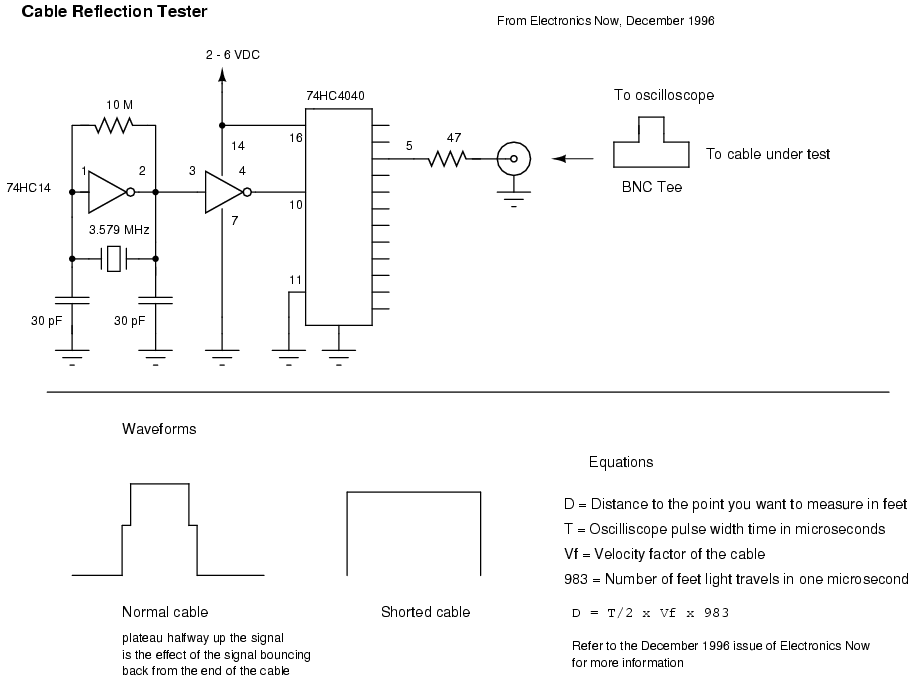
Here is a schematic for a homebrew cable reflection tester from the December 1996 issue of Electronics Now. It's very useful for checking coax cable runs for shorts or even impedance mismatches. It works by sending a pulse down the cable, then checking the return signal on an oscilloscope. You can then determine the distance to a short or impedance mismatch using simple distance = time x speed equations. Be sure to divide your time by 2, and take in account your cable's velocity factor.
Here is a schematic for a homebrew cable reflection tester from the December 1996 issue of Electronics Now. It's very useful for checking coax cable runs for shorts or even impedance mismatches. It works by sending a pulse down the cable, then checking the return signal on an oscilloscope. You can then determine the distance to a short or impedance mismatch using simple distance = time x speed equations. Be sure to divide your time by 2, and take in account your cable's velocity factor.
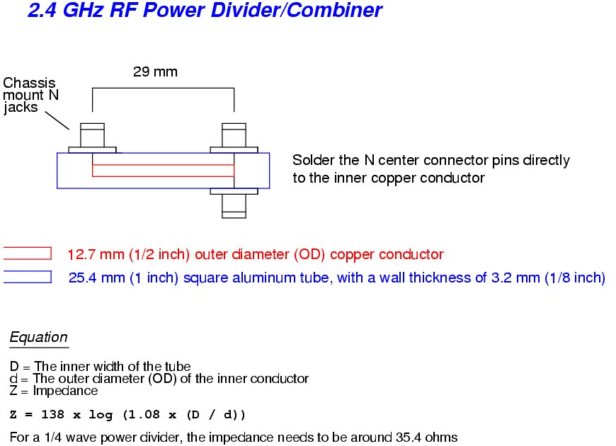
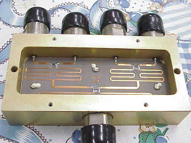
Here is a device called a 2.4 GHz quarter-wave power divider/combiner. You can use this to phase two antennas together for increased gain or combine the input/outputs of amplifier for increased power.
It is possible to use old 800 MHz cellular phone power dividers/combiners at 2.4 GHz because of the 3rd harmonic relationship.
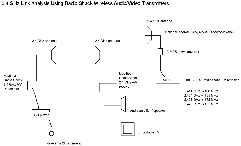
One of the coolest things to do is 2.4 GHz wireless link analysis using those $99 wireless audio/video transmitters from Radio Shack (part number 15-1971). They transmit about 1 mW on the frequencies of 2.411, 2.434, 2.453, and 2.473 GHz. They can even be modified for an external antenna output jack, just like the Symphony, and can also have their output RF power increased to around 60 mW. Refer to this site for a how-to and schematic for that modification.
You can then use a portable CD player and portable audio amplifier/speaker to verify that a 2.4 GHz link is possible in the enviroment you're testing. It's not an entirelly accurate analysis do to the narrow bandwidth of audio, but should still be useful.
- Link Analysis Using Wireless A/V Transmitters
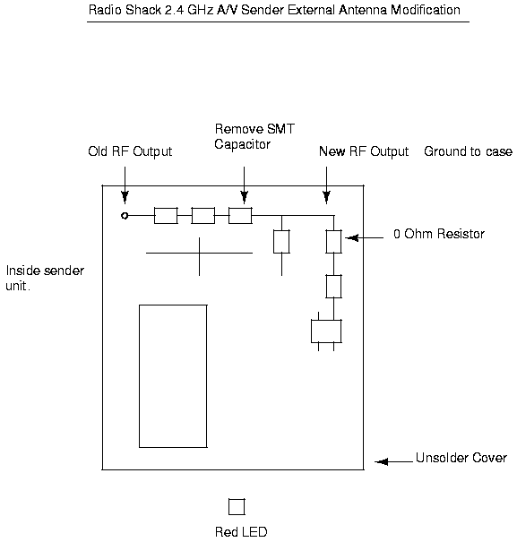
- 2.4 GHz A/V Transmitter External Antenna Modification For the Radio Shack units, which are slighty different.
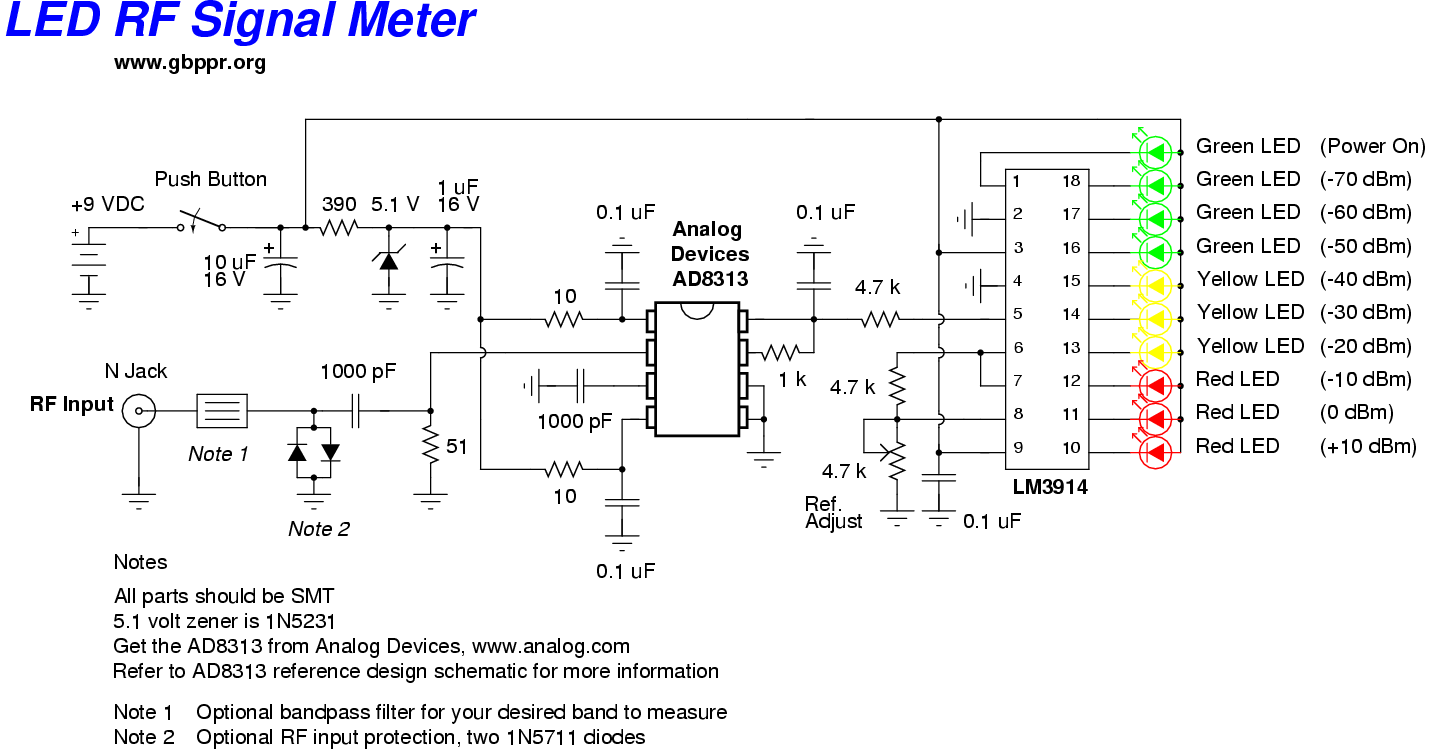
This is a high quality RF signal meter based around the Analog Devices AD8313 0.1 GHz - 2.5 GHz logarithmic detector IC. It is capable of detecting signals as low as -80 dBm. When combined with 2.4 GHz or 915 MHz bandpass filters, it makes a quick visual reference to the amount of noise in the ISM bands in that particular location.
It also makes a handy visual tool for verifying that your antenna is indeed radiating energy.
- LED RF Signal Meter Schematic
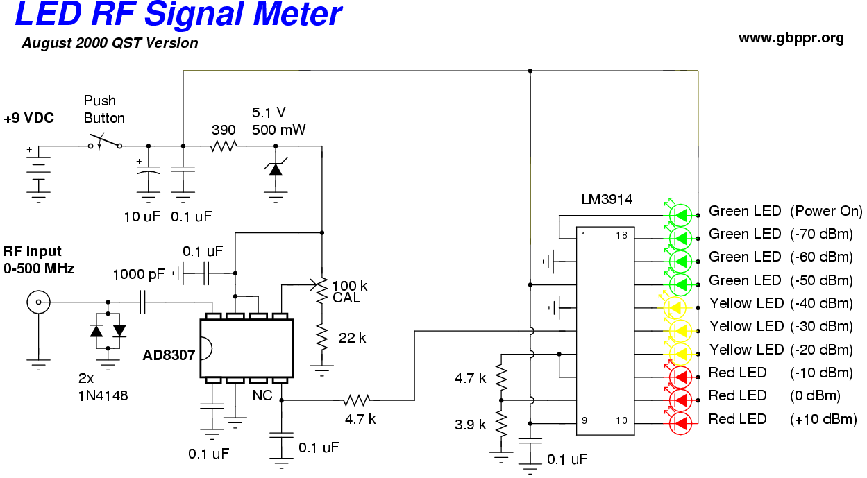
- LED RF Signal Meter Schematic 500 MHz QST version (20k PostScript)
- Pictures of the LED RF Signal Meter
- Analog Devices AD8313 Datasheet (267k PDF)
- 1 MHz to 950 MHz RF Wave Absortion Meter With LED Signal Indication
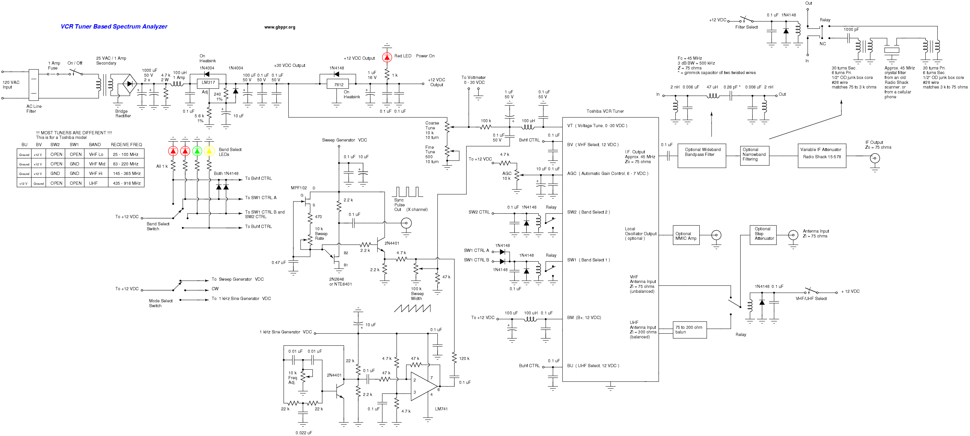
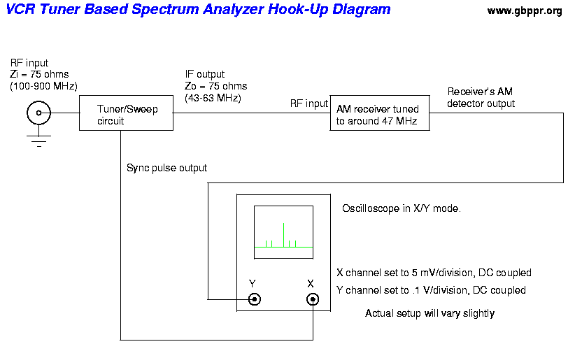
Here is a homebrew spectrum analyzer you can build using an old VCR tuner module. Frequency coverage will be from around 80 MHz to 920 MHz and varies slightly with tuner manufacturer. It will also require an old oscilloscope that is capable of X/Y mode with DC input and a receiver which can tune around 47 MHz AM and can also be modified to tap its AM detector.
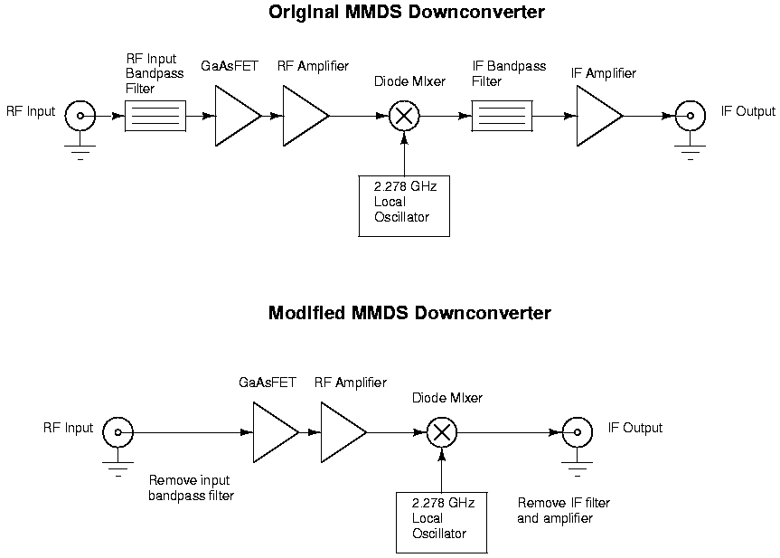
It's even possible to downconvert a 2.4 GHz signal down to VHF frequencies using a slightly modified MMDS downconvter. This will allow you to view 2.4 GHz signals with this analyzer.
This particular project will be better documented in time ...
Quick notes: The display is not logarithmic, only about 10 MHz can be displayed at a time, the traces are big and fat because of no narrow-band filtering (crystal 45 MHz IF filters from cellular phones will fix this), VCR tuners have *alot* of internal noise (at least mine does), every VCR tuner I have messed with was different in some way.
New and improved version is located here.
- VCR Tuner Based RF Spectrum Analyzer Schematic
My Toshiba VCR tuner oscillator/tuning plots- VCR Tuner Based RF Spectrum Analyzer Hook-Up Diagram
- RF Input Step Attenuator Schematic
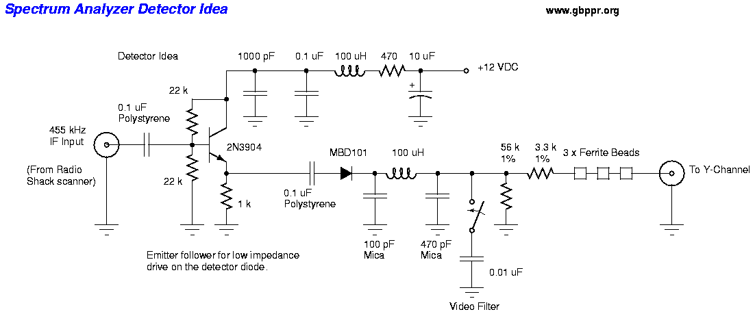
- RF Detector Circuit Idea
- VCR Tuner Based RF Spectrum Analyzer Pictures
- A Spectrum Analyzer for the Radio Amateur August 1998 issue of QST. (400k PDF)
- A Spectrum Analyzer for the Radio Amateur - Part 2 September 1998 issue of QST. (200k PDF)
- W7ZOI Spectrum Analyzer
- W7ZOI/K7TAU Spectrum Analyzer Constructed by N8QOH
- Schematic of a UHF Only VCR Tuner
- Lots of Good Spectrum Analyzer Links and Notes
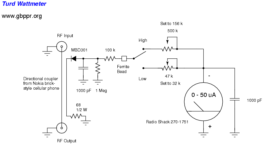
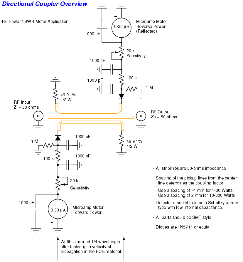
It is possible to make high frequency RF power/SWR (standing wave ratio) meters using homebrew directional couplers and other easily available parts. It is even possible to use the directional coupler and detector diodes from an old cellular phone.
- Pictures of a Homebrew 2.4 GHz RF Power Meter / SWR Meter
- Turd® RF Wattmeter Schematic
Response calibrated against a Bird 43 with 400-1000 MHz / 25 W element
- 300 MHz response
- 350 MHz response
- 400 MHz response
- 450 MHz response
- 500 MHz response
- 550 MHz response
- 600 MHz response
- 650 MHz response
- 700 MHz response
- 750 MHz response
- 800 MHz response
- 850 MHz response
- 900 MHz response
- 950 MHz response
- 1000 MHz response
- 1200 MHz response
- Pictures of the Turd® RF Wattmeter and a Prototype An attempt at a homebrew Bird quality wattmeter
- Directional Coupler Overview
- Bird RF Wattmeter Patent
- Another Bird Patent
- Microstrip Configuration with Inductive Pickup Loop for VSWR Meter Patent
- Digital RF Wattmeter Patent
Return loss (reflection coefficient) bridges are broadband RF comparators. These devices develop a DC potential with respect to ground which is proportional to the degree of unbalance in the arms of the bridge circuit. The bridges provide DC isolation to prevent undesired loading of the circuitry by associated test equipment.
Return loss can be measured by taking the DC OUT voltage with Z2 terminated, divided by the DC OUT voltage without any Z2 termination. That value is then feed into the following formula: Return Loss (dB) = -20 * log10(p) where p is the value you determined from above measurement.
Note that Z1 is your reference termination and should be terminated with a non-inductive 50 Ohm load.
In Perl:
    $p = $DC_voltage_terminated / $DC_voltage_not_terminated);
    $rtrnloss_db = -20 * log10($p);
    $SWR = (1 + $p) / (1 - $p);

    Example: Unterminated voltage is 2.0 Volts
             Terminated voltage is 0.8 Volts
             Then the return loss is 7.96 dB or a SWR of 2.33
It is possible to use the return loss bridge to determine the insertion loss of coaxial cable systems. In coaxial cables, the insertion loss is comprised of resistive losses (skin effect) and dielectric losses. Each of these parameters increases with frequency. The insertion loss of a cable system is determined by observing the reflections from an open (or shorted) output.
Cable Insertion Loss Measurement Example:
- Perform the initial return loss bridge calibration. That is, measure the DC output voltage, at the operating frequency, of a unterminated bridge.
- Open (or short) one end of the the cable you wish to test.
- Connect the other end of the cable to the return loss bridge's Z2 port.
- Determine the SWR using the procedure above.
- Refer to this table to correlate SWR to insertion losses.
It is also possible to use the return loss bridge to determine the structural return loss of coaxial cable systems. Structural return loss is basically a measure of the quality of a cable. In coaxial cables, structural return loss is caused by any imperfections in the overall cable system. Reflections will occur from variations in the cable's diameter, dielectric imperfections, sharp bends, center conductor misplacement, stupid people installing connectors, etc. These reflections prevent a certain portion of the forward RF power from ever reaching the antenna system or load.
Cable Structural Return Loss Measurement Example:
- Perform the initial return loss bridge calibration. That is, measure the DC output voltage, at the operating frequency, of a unterminated bridge.
- Terminate one end of the the cable you wish to test with a load matching the cable's characteristic impedance, 50-ohms usually.
- Connect the other end of the cable to the return loss bridge's Z2 port.
- Determine the SWR using the procedure above.
- Refer to this table to read structural return loss in terms of SWR.
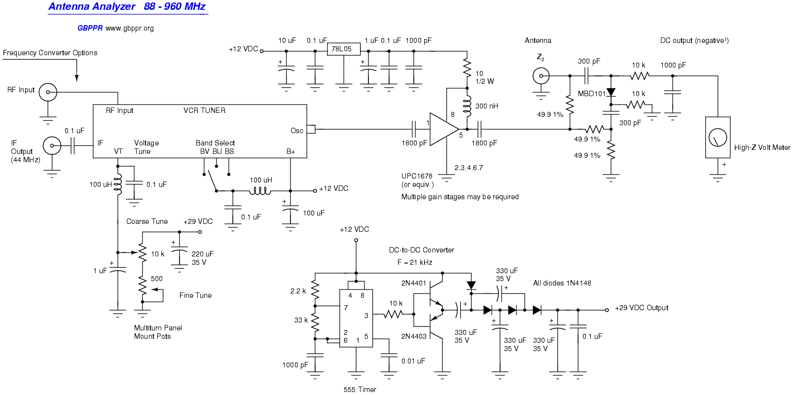
This antenna analyzer is meant to rival the MFJ junk currently on the market. It's still in the prototype stage, but you get the idea how it should work. The oscillator is from an old VCR tuner module. This then drives an amplifier which is connected to a homebrew return loss bridge. When you connect your antenna up to the analyzer, a DC voltage is generated which corresponds to any impedance mismatch. Refer to the return loss bridge section for more information on how return loss bridges work.
Improved antenna analyzer idea.
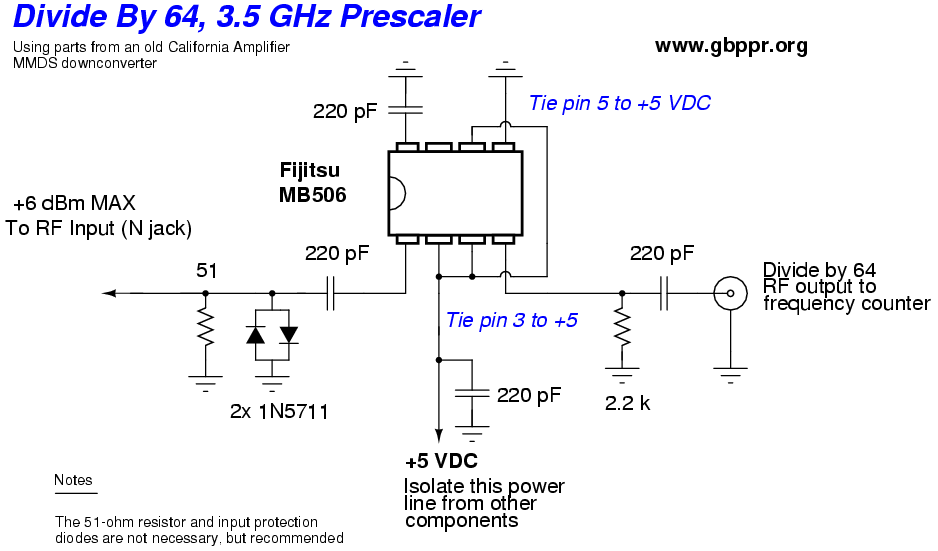
This will take a 0.1 - 3.5 GHz signal and divide it by 1000 so you can measure frequencies outside the normal range of your frequency counter. Example, a 2450 MHz signal will read 2.450 MHz on your counter. This is from the July 20, 2000 issue of EDN magazine and I made a few modifications.
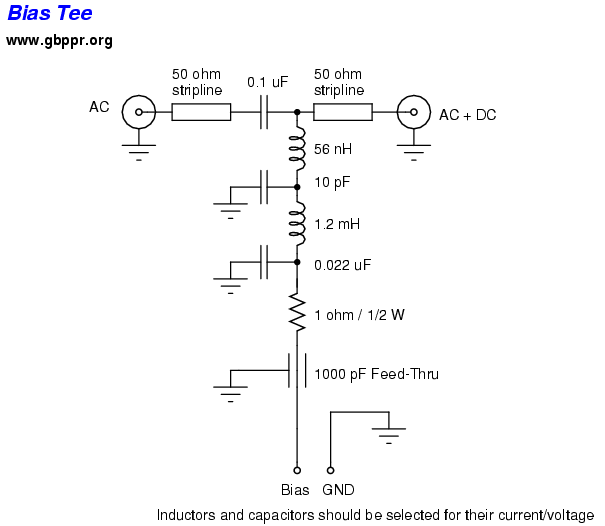
Bias tees allow you to insert DC voltages into your signal path (coax) without disrupting the existing signal in that path.
This version has an input/output impedance of 50 Ohms and should have a low insertion loss from 5 kHz to 3 GHz. The maximum DC voltage and currents ratings will vary with components used (50 V / 500 mA typical). Keep the RF input power under 2 Watts.
Build this simple 50 Watt VHF power amplifier using the power amplifier section of an old Motorola Mocom 70 VHF radio. Adaption to other power amplifier sections should be trivial.
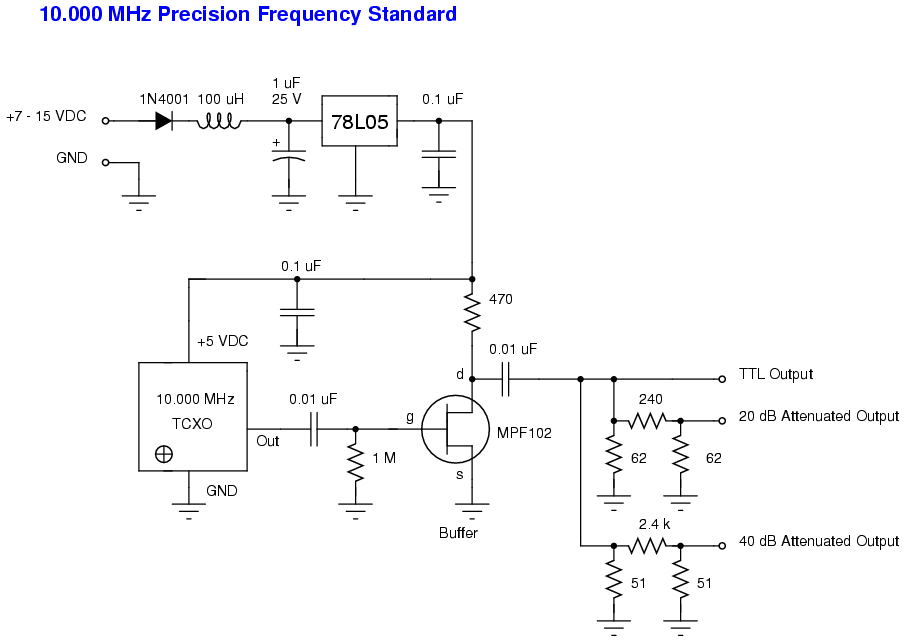
It is possible to build a highly accurate frequency standard using a common 10.000 MHz temperature compensated crystal oscillator (TCXO). When zero-beated against the 10.000 MHz WWV time standard, you will have a reference that is accuate to within a few hertz.
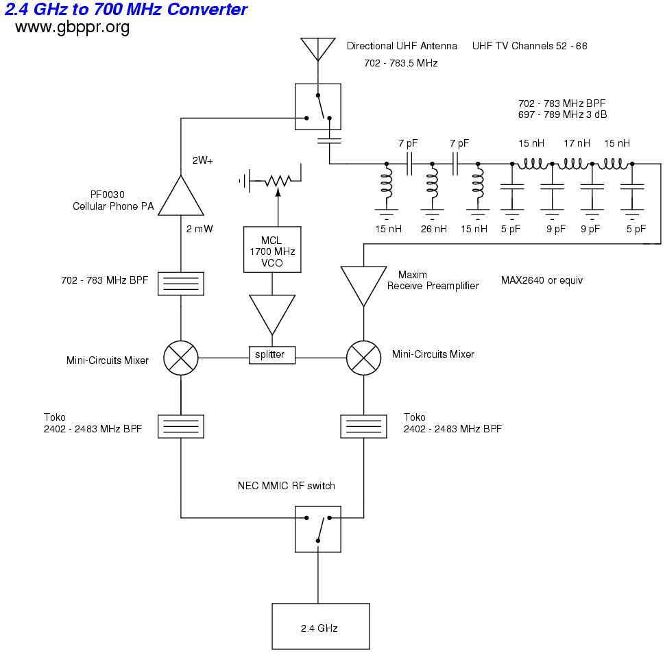
It's theoretically possible to convert a 2.4 GHz wireless LAN signal to a much lower frequency to help overcome non line-of-sight issues. Many UHF television frequencies in some areas are currenty unused. Those would be great to hijack. You could then use common directional UHF TV antennas for your links. This current design is theory only.
It might even be possible to hack the local oscillator out of an old 2.5 GHz MMDS downconverter and use that to drive an external frequency converter.
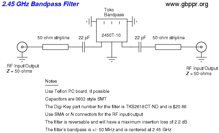
Here is a simple 2.45 GHz bandpass filter you can build yourself for around $30. The pass band is +/- 50 MHz and is centered at 2.45 GHz. Insertion loss is 2.2 dB max. The filter can be purchased from Digi-Key, part number TKS2618CT-ND. The two DC blocking capacitors shown in the schematic are optional, but are needed if there will be DC on the line.
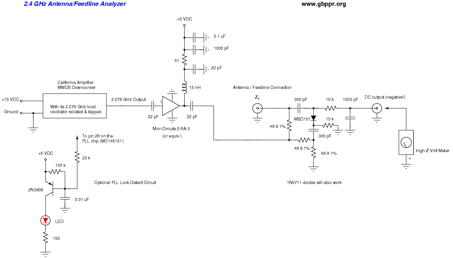
Here is a simple 2.4 GHz antenna/feedline analyzer you can easily build. It's impossible verify that antennas/cables are opertating correctly by using a ohmmeter because they only check for DC continuity. The correct way to verify antennas/cables is at their operating frequency (or close to it). This device is just a return loss bridge and the local oscillator out of an old MMDS downconverter. The downconverter will supply us with a nice, clean 2.278 GHz signal we can use to drive the return loss bridge.
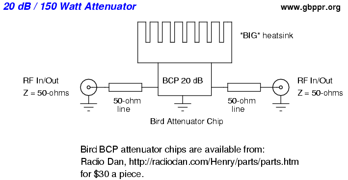
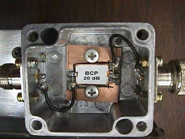
Here is a simple, easy and cheap way to make fairly high power RF attenuators. These are useful for directly connecting the output of a high power RF amplifier into a spectrum analyzer, frequency counter or other piece of test equipment (additional attenuation maybe required!). The circuit is based around a Bird Component Products attenuator chip, which are available from Radio Dan for $30 a piece. When properly heatsinked, they will dissipate a continous 150 Watts of power.
- 20 dB / 150 Watt Attenuator Schematic
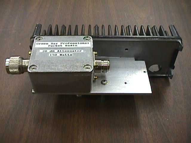
- 20 dB / 150 Watt Attenuator Picture One & Picture Two
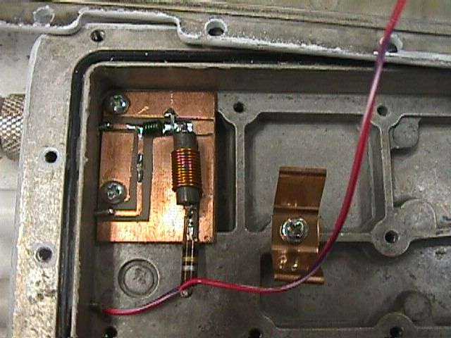
Here is a simple RF probe you can make to measure small RF power levels up through the microwave frequency bands. This version come from Libor Ulcak.
This allows you to quickly verify the integrity of the 2.4 GHz band by downconverting the 2.4 GHz signals to much lower frequencys, and then using a conventional communications receiver (scanner) to step through the new frequency range of 124 - 205 MHz. The receive converter is based around a high-gain model MMDS downconverter with a few simple modifications. This is a real useful piece of test equipment when tracking down narrowband interference in the 2.4 GHz band.
- The FARA Project An economical, easy-to-build, 25 watt 2 meter amplifier
- Advanced Power Technology Application notes
- Application Notes and Reference Materials From Tektronics
- Power Meter/Dummy Load
- Steve's Workshop
- G3PTO
- JF1OZL
- The Museum of Tek Scopes
- RF sampler
- WE6W
- Electronics For You
- 4QD's pages of interesting circuits
- G-QRP Club Technical Pages
- Measuring and testing links
- RL-Circuits Over 5000 links
- Simple Circuits
- Jim's Technical Web Page
- To Design and Build a Portable, Miniaturised, Multichannel FM Transmitter Covers the complete design of a low power FM transmitter
- Toward High Efficiency Power Amps
- Player's Reverse Engineering Tools
- Fravia's archive pages of reverse engineering
- Radio Service Software
- The Alpha Gunnplexer Data links using the demodulator and IF strip is from a 4 Ghz satellite receiver
- DIY Op Amps
- Analog Devices Application Notes
- Burr-Brown: Applications Bulletins
- Linear Technologies - Design Notes
- Motorola Application Notes 2.02
- National Application Notes
- Siliconix Small-Signal FET Application Notes
- The LED Museum
- QRP power meter and dummy load
- R.A.S.O.N Pages
- JG1EAD's Home Page Good spectrum analyzer design
- Lots of good weaksignal/RF links
- Slot Antenna Design by Stephen Bell, KB7TRZ
- SMD Codebook
- Radiated Emissions Measurement Systems Tutorial
- SIGSALY Secure Digital Voice Communications in World War II
- Homebrew General Coverage Radio Receiver
- Ham-Pic Member Projects
Return to the Low Cost Wireless Network How-To