QRP Field Operations

POLAR BEARS MOONLIGHT MADNESS EVENTS
POLAR BEAR #126
The Polar Bears Group is a great bunch of guys and provide alot of fun for the portable operator during the winter months.
POLAR BEARS WEBSITE
N9SKN YouTube Channel
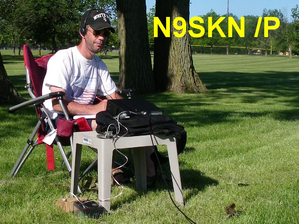
I have been enjoying the challenge and fun of
operating outdoors at different locations. I think there are two kinds of portable Op's that I am interested in.
1) Reaping the benefit of a QRP signal thats as big as possible - due to the opportunity to deploy better antennas than I can erect in the space at my home QTH. Performance is primary, convenience and time is secondary.
2) True 'portability' style of operation. The ability to setup a small station just about anywhere. Performance is secondary here, getting on the air from any location as conveniently and quickly as possible is primary.
Portable equipment list includes:
- a 10m CW trans-receiver based on K8IQY "Iowa10" RX and a W1FB TX
- Sierra from the ARRL Handbook (80-15m)
- Emtech ZM-2 tuner
- Sears 'Diehard Portable Power 750' 12 volt supply
- Home made slingshot/ fishing reel antenna launcher
- 10m Moxon beam antenna on painters pole
- 40M house wire dipole fed with RS low loss twinlead
- 80M speaker wire dipole fed with RS low loss twinlead
- 27ft. wire vertical ground plane supported by a 31ft. Jacktite fiberglass pole with the compliment of ground radials. The ZM-2 is mounted at the base.
- End fed half wave wire antennas (EFHWA) for 20, 30, 40 meters.
- Homebrewed EFHWA Tuner
- 30m Bobtail vertical array
- 40m Half Square vertical array
- VE7CA 15/20m wire yagi
- 15/17/20/30/40m shortened, hatted vertical dipole (SHVD) based on design of Kurt, ON4BAI
After completing the Sierra build and going out 'solo' during the summer of 2008, I joined the Polar Bears of the Eastern PA Radio Club during the fall. These guys go out once a month in winter time and try to contact the other Polar Bears. I think its kind of a 'Extreme Hamming' outdoors in the cold, but was the most fun I had in a very long time and look forward to doing it again.
Some portable QTH's:
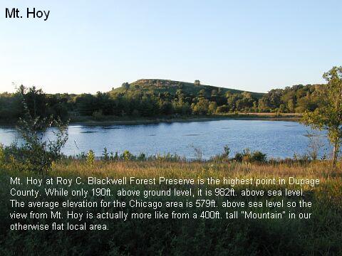
I have
operated portable from this location once already, using the
31ft. Jacktite fiberglass pole supporting a 27ft. vertical wire
along with the associated ground radials. I made it as far as San
Francisco with 2w on 20 meters. We don't have much in the way of
mountains in IL, so this was as close as I can get ;)
The view from on top is really pretty spectacular for around here.
This area is about 10 miles from my QTH.
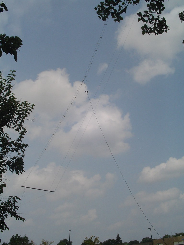
I remove the top whip section from the Jacktite pole and a 1/2" plumbing elbow with a few inches of stiff plastic tubing over one end fits over the top of the pole. There is a rubber band attaching the wire to the tubing to provide a light tension on the wire. I tried unsuccessfully lengthening the wire to 30ft. It would not tune on any of the bands with the ZM-2 tuner, but 27ft. works nice and has repeatable tuner settings that allow for complete extinguishing of the SWR LED for 40, 30, 20, 17 meters - no matter where I have put the antenna up. This has saved me on setup time and battery life. I keep reading that dipoles have more gain, and verticals are the worst choice for QRP'ers. However, in my opinion so far this antenna has provided for many more callbacks to my CQ than my original 44ft Norcal Doublet, and not just from Mt. Hoy.
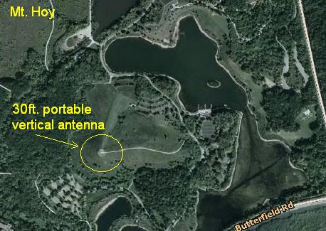
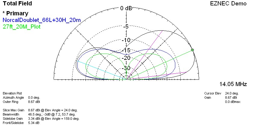
The 27ft fiberglass supported vertical wire plot is below. This is the antenna for when there are no trees, or when I want to operate at areas where wires are not allowed in trees (Like the entire county forest preserve system here).


The view from on top is really pretty spectacular for around here.
This area is about 10 miles from my QTH.
I remove the top whip section from the Jacktite pole and a 1/2" plumbing elbow with a few inches of stiff plastic tubing over one end fits over the top of the pole. There is a rubber band attaching the wire to the tubing to provide a light tension on the wire. I tried unsuccessfully lengthening the wire to 30ft. It would not tune on any of the bands with the ZM-2 tuner, but 27ft. works nice and has repeatable tuner settings that allow for complete extinguishing of the SWR LED for 40, 30, 20, 17 meters - no matter where I have put the antenna up. This has saved me on setup time and battery life. I keep reading that dipoles have more gain, and verticals are the worst choice for QRP'ers. However, in my opinion so far this antenna has provided for many more callbacks to my CQ than my original 44ft Norcal Doublet, and not just from Mt. Hoy.
The 27ft fiberglass supported vertical wire plot is below. This is the antenna for when there are no trees, or when I want to operate at areas where wires are not allowed in trees (Like the entire county forest preserve system here).
Some more pictures of my first visit to Mt. Hoy below.


This ground plane vertical has also made
an appearance at another local 'summit', The landfill hill at Green
Valley Forest Preserve that is second in height in the county only
to Mt. Hoy (Above). This was a great spot to visit as there is a
washroom and picnic tables at the top, and you can drive up there.
I hear it is often crowded though, and its only open in the afternoons, and only on the weekends, and only the warmer months of the year.
I'm definately going back there though!
I hear it is often crowded though, and its only open in the afternoons, and only on the weekends, and only the warmer months of the year.
I'm definately going back there though!

I did not pick the best day as far as
the weather for my first visit to Green Valley Hill. The temp was 49F
but the winds were 25-30mph at the top. The Jacktite pole collapsed
into itself once from the counter force of the guy lines. Check out the
bow in the pole and wire that are both normally straight. Like I told
one of the guys on the air, I felt like I was in Antarctica!

This antenna has also been to Hidden Lake Forest Preserve (Picture below). Luckily, the Park Ranger had no problem with it.

Hey, this time its a 40m dipole up about 45ft at Madison Meadow park here in Lombard (Below).
Nice view while operating at the same time.

Below its the 40m dipole again, up 60ft in the magnificient trees at Lake Ellyn Park - one suburb over from my home QTH.

Well I have to keep fooling around with antennas as I do, and selected the "Tri-band 2 Element Portable Yagi"
design by Markus, VE7CA published in the ARRL article. This would be my
first beam antenna and it would open up a whole 'nother can of worms to
play and experiment with.
In a few days spare time during the week I constructed the antenna at the workbench, then preliminary rigging was accomplished (Barely) between two trees in the backyard at home.
I elected to not include the 10m parts of the antenna to reduce weight and since I have never even heard a pin drop on 10m here.
However, this was a carefully balanced and tuned multiband assembly, I was not sure removing the 10m items could be accomplished. A quick check in the EZNEC demo software showed that removing the 10m elements would still preserve the 20 ohm impedance presented to the beta match on 15m and 20m.
Since this would not be a permanently installed antenna, I elected to use 1x2's for the end pieces instead of the 2x2's as suggested for weight savings. I painted my end pieces black for some stealth with a leftover spray can. The hardware store cut a piece of 3/16" plexiglass for $.50 that I could use as a center insulator on the driven elements. For the beta match stubs I used 2 pieces of brazing rod for $.69 each.
The matching stubs and wire element ends were all crimped then soldered with ring terminals. A pair of alligator clips wired together served as the temporary
shorting bar to check the proper position for best match on the lower part of 20m (I don't have a 15m band module for my portable rig yet).
I fed it with 57ft of RG-58 (7ft is used in the choke coil).
Lowest SWR was obtained just 3/8" away from Markus's dimension in the article and a piece of 1/16" copper coated welding rod was soldered permanently in place for the shorting bar.
For final balancing and initial tuning, I had the antenna deployed on a 45 degree angle with center feed point at about 30ft up and launching west out of the Chicago area. After 30 minutes on 14.060 I had a pair of 2X QRP QSO's to AZ and another to NV with my 2 watts - so it was working fine. I was back home about 45 minutes later that afternoon and could hear next to nothing on 20m from the base station - so I think the antenna did a good job so far in the poor afternoon band condx that day.
Learning to use a beam antenna will be interesting as I already noticed it occurred more often that I could hear only one side of a QSO with this antenna.
The antenna does not rotate instantly - so adjustment during a QSO is out of the question. I will have to pick a zone and stay with it until leaving the operating position again for any adjustments. Also this antenna cost me about 45 minutes untangling it when I got to the test area (I did not roll it, just bagged the ends).
I highly recommend ROLLING it up as Markus suggests - then all is fine.
For a 45 degree sloped deployment, this antenna requires only one tree support instead of two (As in a dipole). One tree is a plus around here.
Also just a 90 degree swing radius around the top support is needed for full 360 degree coverage. Changing directions 180 by pulling on the feedline works nicely as Markus described, by just pulling on the feedline so the whole antenna rolls over. Some pictures of this antenna below.
This antenna maybe a bit more work to manage, but the plot below shows the benefits of any extra work compared to my other antennas on 20m, and 15m should be respectable as well.
I have begun
experimenting with the end fed half wave antennas (EFHWA) for portable
operating now as well. I have found that the colder it is outside the simpler the antenna, the better. The EFHWA antennas substantially reduce my setup time compared
to the other types. I ran into an EFHWA
design by WB3GCK called the "Dollar Store Special"
and started looking at it in the EZNEC demo. I thought his use of
modular counterpoise wires to change lengths was clever. The 50ft
length of that design did not look too good to me at 20meters in the
modeling software though.
So I made 3 half wave wires for 20, 30, and 40 meters that I use with single 1/4 wave counterpoises and so far the on air results have been great. I can now understand why I have read about QRPers liking the end fed half wave antenna so much. They are comparitively quick and easy to deploy and take down, and small and lightweight.
The Emtech ZM-2 tunes these half wave antennas with their respective counterpoises just fine (Although it does not claim to).
However after reading up on tuners, I began to worry about the ZM-2 losses matching 50 to 2000 ohms. I had read that losses become very significant when trying to match above 500 ohms on most tuners, so I looked around online for some more ideas and maybe a better way.
I think I found it at AA5TB's website . I liked that he tested his matching network and had only .5dB of loss and he explained his methods well for this type of antenna/matcher setup. So I decided to try it out for myself. My goal was one tuner box for 20, 30, and 40m.
Looking at the EZNEC demo I modeled the EFHWA's for the three bands using the exact wire gauge of the antennas I had with quarter wave counter poises and came up with the impedances 1836, 1960, and 2032 ohms. I selected a turns ratio of 3:19 that would equate to 2004 ohms.
I did not have any poly varicons, but did have several air variable caps in the junk box. I selected one of the RX type of air variable caps I had that had about the same range as the poly varicons. I found most guys online used a -2 mix toroid for the matching transformer and I happened to have a T-130-2 in junk box as well! I love junk box projects - they are just the best.
I wanted to include a SWR indication LED circuit though to keep this as a 'minimalist' antenna so I did not have to bring seperate metering.
I was lucky that I could grab some 1W 200 ohm resistors, and a clear LED at a local Frys store for the Tayloe SWR Bridge, and a plastic box at RS. I did not have an FT-37-43 core, but substituted a FT-50-43 core out of the junk box for the detector circuit using the same turns. Although AA5TB states the magic counterpoise length is .05 wavelenths, I could not duplicate this in EZNEC - which with my limited abilities in the software is not all that surprising. So I stayed with the standard quarter wave counterpoise lengths. I elected to use bullet connectors to form one 40m quarter wavelength counterpoise out of the 3 lengths neccessary for all three bands, and remove sections as needed for 20 and 30m.
Pretty happy guy when it all worked and the light went out, but it is not perfect all the time. At the third location I was using this antenna at I had some trouble matching it. I have found in portable operating that a tuner is almost a must because every operating location is different and what works nicely at one spot may not match up good at another. This is just as true with dipole deployed heights as I also found it to be with this antenna set. So I have made an extra two foot length of wire to be attached at the top of the antennas or at the end of the counterpoise with bullet connectors should it be neccessary for a good match. Using this extension wire as needed, or selecting different combinations of the three counterpoise wires has been successful so far and I have made the contacts with this setup to prove it and now join the choir of QRP portable Op's who sing their praises of the end fed half wave antenna.
************
UPDATE Fall 2008 ON THE EFHWA TUNER: Well I finally ran into a situation that I could not match wire combinations on ANY band. This was after the ground froze and was also covered with several inches of snow. So I decided to rewind the secondary of the transformer with taps at 17, 18, 19, 20, and 21 turns through a rotary switch to provide some additional matching range. Right now I am thinking that frozen ground and / or snow cover really affects the impedance of this kind of antenna.
************
UPDATE Spring 2009 ON THE EFHWA TUNER: What do you know? I have been out again to 2 of my favorite same spots and all 3 (20, 30, and 40m) half wave wires are tuning fine once again with the dedicated tuner shown below. There is definately some interaction between the frozen ground or snow and the impedance of the half wave antenna that puts it 'out of the ball park' of my dedicated EFHWA tuner. The ZM-2 still tunes the wires in any weather - though with some variances of the recorded settings..
************
Thanks to AA5TB for sharing some great antenna ideas (He no longer publishes his email address as he was swamped with emails). Now I can worry about other things besides tuner loss at high impedances.
Below are some pictures of my EFHWA tuner during verification testing of the bridge with a SWR meter in line at the park. I use a piece of heavy duty 3M velcro on the back of the tuner and attach it to a plastic tent stake in the ground.

This is the plot for the 66.5ft EFHWA below. The 20 and 30m plots are similiar. This is the antenna for when there is not 2 large trees located together suggesting a dipole install, when time is more limited, its very cold, or I anticipate being out after dark.

So I made 3 half wave wires for 20, 30, and 40 meters that I use with single 1/4 wave counterpoises and so far the on air results have been great. I can now understand why I have read about QRPers liking the end fed half wave antenna so much. They are comparitively quick and easy to deploy and take down, and small and lightweight.
The Emtech ZM-2 tunes these half wave antennas with their respective counterpoises just fine (Although it does not claim to).
However after reading up on tuners, I began to worry about the ZM-2 losses matching 50 to 2000 ohms. I had read that losses become very significant when trying to match above 500 ohms on most tuners, so I looked around online for some more ideas and maybe a better way.
I think I found it at AA5TB's website . I liked that he tested his matching network and had only .5dB of loss and he explained his methods well for this type of antenna/matcher setup. So I decided to try it out for myself. My goal was one tuner box for 20, 30, and 40m.
Looking at the EZNEC demo I modeled the EFHWA's for the three bands using the exact wire gauge of the antennas I had with quarter wave counter poises and came up with the impedances 1836, 1960, and 2032 ohms. I selected a turns ratio of 3:19 that would equate to 2004 ohms.
I did not have any poly varicons, but did have several air variable caps in the junk box. I selected one of the RX type of air variable caps I had that had about the same range as the poly varicons. I found most guys online used a -2 mix toroid for the matching transformer and I happened to have a T-130-2 in junk box as well! I love junk box projects - they are just the best.
I wanted to include a SWR indication LED circuit though to keep this as a 'minimalist' antenna so I did not have to bring seperate metering.
I was lucky that I could grab some 1W 200 ohm resistors, and a clear LED at a local Frys store for the Tayloe SWR Bridge, and a plastic box at RS. I did not have an FT-37-43 core, but substituted a FT-50-43 core out of the junk box for the detector circuit using the same turns. Although AA5TB states the magic counterpoise length is .05 wavelenths, I could not duplicate this in EZNEC - which with my limited abilities in the software is not all that surprising. So I stayed with the standard quarter wave counterpoise lengths. I elected to use bullet connectors to form one 40m quarter wavelength counterpoise out of the 3 lengths neccessary for all three bands, and remove sections as needed for 20 and 30m.
Pretty happy guy when it all worked and the light went out, but it is not perfect all the time. At the third location I was using this antenna at I had some trouble matching it. I have found in portable operating that a tuner is almost a must because every operating location is different and what works nicely at one spot may not match up good at another. This is just as true with dipole deployed heights as I also found it to be with this antenna set. So I have made an extra two foot length of wire to be attached at the top of the antennas or at the end of the counterpoise with bullet connectors should it be neccessary for a good match. Using this extension wire as needed, or selecting different combinations of the three counterpoise wires has been successful so far and I have made the contacts with this setup to prove it and now join the choir of QRP portable Op's who sing their praises of the end fed half wave antenna.
************
UPDATE Fall 2008 ON THE EFHWA TUNER: Well I finally ran into a situation that I could not match wire combinations on ANY band. This was after the ground froze and was also covered with several inches of snow. So I decided to rewind the secondary of the transformer with taps at 17, 18, 19, 20, and 21 turns through a rotary switch to provide some additional matching range. Right now I am thinking that frozen ground and / or snow cover really affects the impedance of this kind of antenna.
************
UPDATE Spring 2009 ON THE EFHWA TUNER: What do you know? I have been out again to 2 of my favorite same spots and all 3 (20, 30, and 40m) half wave wires are tuning fine once again with the dedicated tuner shown below. There is definately some interaction between the frozen ground or snow and the impedance of the half wave antenna that puts it 'out of the ball park' of my dedicated EFHWA tuner. The ZM-2 still tunes the wires in any weather - though with some variances of the recorded settings..
************
Thanks to AA5TB for sharing some great antenna ideas (He no longer publishes his email address as he was swamped with emails). Now I can worry about other things besides tuner loss at high impedances.
Below are some pictures of my EFHWA tuner during verification testing of the bridge with a SWR meter in line at the park. I use a piece of heavy duty 3M velcro on the back of the tuner and attach it to a plastic tent stake in the ground.
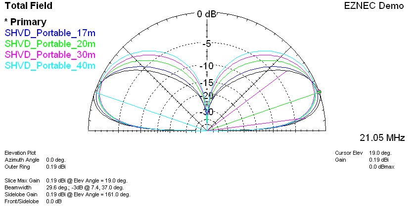
This is the plot for the 66.5ft EFHWA below. The 20 and 30m plots are similiar. This is the antenna for when there is not 2 large trees located together suggesting a dipole install, when time is more limited, its very cold, or I anticipate being out after dark.
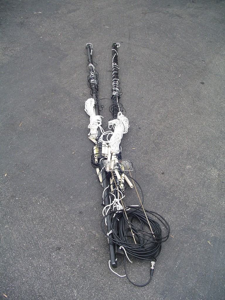
A portable "Shortened Hatted Vertical Dipole" (SHVD) for 15, 17, 20, 30, and 40m is below.
"An antenna for guys who like antennas"


Well since I noticed some tuning changes on my EFHWA set of antennas and even my vertical ground plane antenna was acting different on the snowy, frozen ground at the same operating locations as when it was warmer, I began to look for an alternative, self-supporting antenna project that might reduce the ground losses changing with the snow and frozen ground here during winter portable operation. After looking around at some different theorys, ideas and antenna designs, I was intrigued with the vertical dipole as a possible solution, particularly the short, hatted version since I wanted a portable and self-supporting antenna.
I ran into a multi band SHVD design by Kurt, ON4BAI that was rather compact. His reference of L.B. Cebik's article "Verticals Without Vertigo" was enlightening on the short, hatted vertical dipole. Mr. Cebik stated that this type of antenna should have a radiation pattern approximately the same as a full sized 1/4 wave radiator with 16 radials. I also asked Dan, N3OX about any efficiency or performance shortcomings this type of antenna may have compared with a ground plane 1/4 wave vertical. N3OX selflessly provided his input and could see nothing wrong with construction of such an antenna, although he did point out some similarities to the commercial Force 12 Sigma 40XK, and the Trans World Antennas TW2010.
Any antenna I made would have to be self-supporting, easily dis-assembled and re-assembled for portable use, of reasonable cost and weight, and ideally constructed of readily available & common hardware store materials. The SHVD in the article was nicely constructed of all aluminum, but for me aluminum was not readily available, was cost prohibitive, I had no capability to weld it, and that design did not appear to disassemble that easily or into small enough sections for portable use.
So after considering some local material choices, then spending time in EZNEC Demo modeling my version of the antenna as closely as I could, I came up with some antenna component lengths that appeared would provide for multi band operation on the higher bands by changing around the number of hats and tuning stubs on the end of the hats. 30 and 40 meter operation would be configured using simple R.S. DPDT switches.
This antenna is 16ft tall and mounted as modeled with the bottom hat 4ft above ground for an overall height of 20ft.. It was constructed of 4 seperate 3/4" EMT electrical conduit 4ft vertical sections using 3/4" EMT couplings between the inner and outer sections. The hats were of 1/2" non-metallic (PVC) electrical conduit supporting the 14ga solid hat wiring. The hat centers were small octagonal "J boxes" with the 4 neccessary 1/2" non-metallic box couplings and a coupling on the top that accepted the 3/4" vertical pieces. The tuning stubs were just 1/16" welding rod with a "U" terminal and dogleg bent into the end. For 17m, a different lengthed pair of stubs was made with 90 degree bends to allow vertical orientation and mounting on the hat center boxes.
The center section main loading coils were just PVC forms notched every 1/4" to maintain the wire spacing. The 1/4" notch pattern was staggered 1/8" on the opposite side of the form to allow for winding. For joining the top and bottom vertical conduits I removed a 3/8" section lengthwise from a 12" piece of 1" sched 40 PVC, then installed, heated, and clamped it over a 3/4" piece of conduit with hose clamps and let it cool. The feed is routed through a 1:1 QRP balun mounted on the plexiglass.
I have just started using this antenna on the air to make some contacts after initial tuning on the front lawn. Is it a compromise antenna? Yes, but so is my other portable, self-supported HF antenna. I plan to continue using it regularly for evaluation of its performance as compared to my 27ft vertical ground plane. It is more expensive (under $100) and heavier than the Jacktite vertical, and there is more wind loading. The band changing requires more time than just tweaking the tuner on the Jacktite vertical. It sets up and tears down a little quicker though, and I don't have to play with radials in the snow. As usual I learned alot.
I think this is "An antenna for guys who like antennas" :)
************
UPDATE 03/2009: Without any actual A/B switch comparisons, after using the SHVD for 3 portable outings now, I am comfortable saying that as far as I can tell the SHVD works as good or better than my 27ft vertical ground plane antenna on 20, 30, & 40m. I am figuring that the ground loss is reduced and radiation resistance increased since the feedpoint is 12ft higher, the Q of the 2.375" coils is better than just going through a tuner on 30 and 40m, and also it takes less of that inductive loading anyway for a match due to the additional (And efficient) loading of the capacity hats and stubs.
This antenna can be difficult to erect in the wind and is on the heavy side for hauling out to the field since I used the EMT electrical conduit to keep costs down. Still I think it's modular design is a perfect compliment for the modular Sierra rig.
************
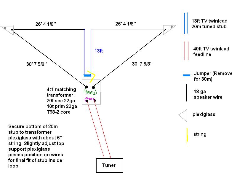
If I were on a DXpedition at some atol - these would be the cats meow.
My favorite current portable antenna is a hombrewed SuperLoop 40 deployed as an inverted delta shape and fed at the bottom with twinlead. This antenna shines on the air as a 20m Bi-Square while still providing respectable results on 30 and 40m in a smaller than dipole length. It provides an approximate 50 ohm match on the 3 bands (A jumper is removed for 30m operation).
Here is a 10 meter CW
trans-receiver I worked on in 2011. It was based on the "IOWA 10" RX by
K8IQY and a W1FB VXO TX. Successful 10 meter circuit construction was a
bit harder than I thought but wanted to give that band a try. I used an
old first aid kit as the enclosure. This rig includes a Tick keyer. I
have made several contacts into Europe and South America with the rig
using the Moxon antenna on a painters pole. A challenging project but
very rewarding. K8IQY was very helpful once again during construction
and testing of the RX.


Thanks for checking out my portable operations page.

Contact N9SKN