On the Occupied Bandwidth of
CW Emissions
© 2003, Douglas T. Smith Editorial
Services
Where the ARRL Handbook and some manufacturers
went wrong.
Introduction
Much
ado has been made lately about the occupied bandwidth of SSB phone
emissions. 3 kHz or so of bandwidth, accompanied by typical levels
of IMD products, has been the acceptable norm for a long time now.
Much more than that on a crowded band tends to raise objections.
What is the acceptable norm for CW emissions?
Part 97
of the FCC rules states that emissions "… shall not occupy more
bandwidth than necessary for the information rate and emission type
being transmitted, in accordance with good amateur practice." (47
CFR 97.307a) A reasonable definition of good amateur practice
includes the avoidance of waveforms that produce objectionable
levels of interference to other users. Why then do we put up with
commercial transmitters that consistently demonstrate such
waveforms?
I postulate that the production of
offensive CW signals is caused by one of two things, or both: 1)
inconsiderate operators, or 2) ignorance on the part of equipment
designers about the optimal CW waveform. The first thing must be
left to our intrepid federal law-enforcement officials; I attempt to
address the second in what follows.
One Wrong
Way
For many years, the ARRL Handbook has
published a figure in Chapter 12 with the caption, "Optimal CW
waveform." In recent editions, it is Fig 12.20, whose shape is
reproduced here as Fig 1. Even a cursory analysis reveals it to be
far from optimal.

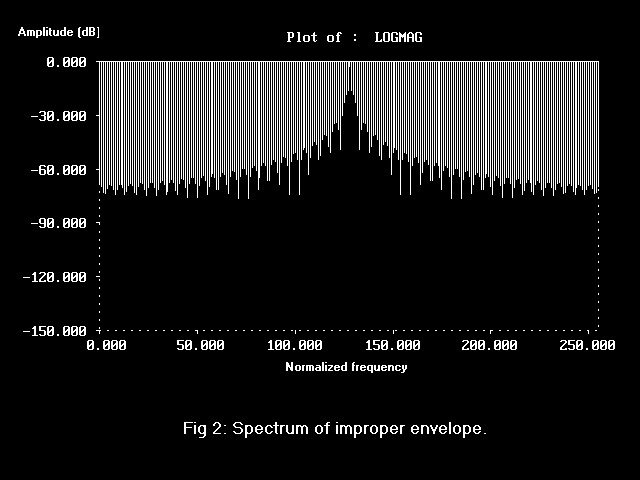
Granted, such an envelope can be produced by
a simple R-C network. Rise and fall times may be controlled by the
time constant of the network. The trouble is that such an envelope
produces significant and unnecessary keying sidebands. It does that
because it contains amplitude discontinuities; its amplitude does
not change smoothly as it begins rising or falling. It has abrupt
changes in its slope at those points.
Fig 2 is a
spectral analysis of the waveform of Fig 1. Spectral occupancy is
chiefly determined by the envelope shape and not by the keying
speed. To be sure, keying such a waveform at high speed puts more
energy into adjacent frequencies than at low speed; but the
instantaneous amplitude of the keying sidebands is constant during
the rise and fall times, regardless of keying speed.
Well, the
Ten-Tec Orion does it better!
The Right
Way
Fig 3 is a depiction of the ideal CW keying
envelope. It rises uniformly from zero amplitude to its maximum; it
also falls smoothly from there to zero. Envelope shape is
sinusoidal; it is called "raised-cosine" keying, which is very close
to the shape occupying minimum bandwidth.

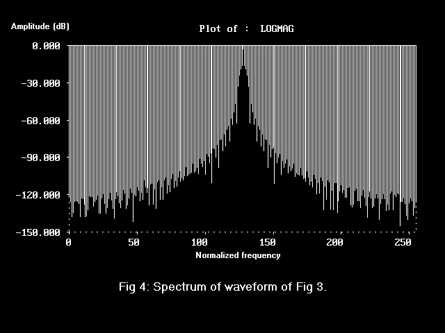
Fig 4 is a spectral
analysis of the waveform of Fig 3. By comparison with Fig 2, note
that modulation sidebands have decreased in amplitude by a large
factor. Digital signal processing (DSP) readily allows designers to
implement such a keying envelope. Admittedly, it is difficult to
achieve with traditional analog electronics; but for DSP-based rigs,
it is relatively simple. Why then don't we see such waveforms from
modern production radios generally?
ALC
Effects
One reason is that automatic level control
or ALC in a transmitter may modify the transmitted envelope. The job
of ALC is to reduce drive to the final power amplifier in a
transmitter so that it is not overdriven. In other words, it sets
the maximum power output.
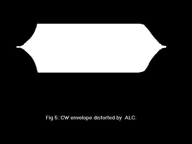
It follows that more drive
than necessary to reach that maximum output power is initially
applied. ALC reduces drive rapidly when the maximum is reached. That
effectively shortens the rise time of CW elements because the attack
time of ALC is fast. ALC decay time is usually slow, so the fall
time is not usually affected by ALC. The result is an envelope
resembling Fig 5 that has a sharp change of slope at the power set
point.
Transmit gain control
or TGC is an algorithm that largely avoids envelope distortion. It
does that by reducing drive over time so that ALC does not have to
work so hard. Drive is adjusted slowly-- more slowly than in ALC--
such that excess drive does not exceed a dB or so. Sharp slope
changes caused by ALC are thus mitigated. More information about TGC
can be found at www.doug-smith.net/digitalagc.htm.
Conclusion
Certain
production rigs could produce better CW envelopes than they do. If
we are serious about 47 CFR 307a, let us apply it consistently
across the variety of different modes, including CW. Our
publications ought to indicate what is best without ambiguity.
Perhaps then equipment designers would wake up and smell the
coffee-- Doug Smith,
KF6DX. |
 Douglas T. Smith Editorial Services