|
BENCH TESTING
After applying DC power to the unit you should
hear several relay clicks and the current consumption should settle around 600
mA. The tuner has two voltage regulators:
4.0 Volt analog bias voltage is
derived from + 8 Volt line. | |||||||||||||||||||||||||||||||||||||||||||||||||||
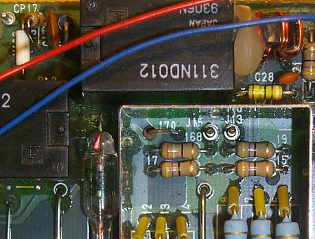
| DEFAULT STATE: After power-up, all relays should default to a RF bypass path, which you may verify by probing voltages on J5, J6 and CP17: | |||||||||||||||||||||||||||||||||||||||||||||||||||
| |||||||||||||||||||||||||||||||||||||||||||||||||||
| In the default
state, the voltages on J5 pins 3 to 12 should be all low (about 0.8 V),
corresponding to all relays enabled, shunting the series inductors. Note
that the 0.8 Volts is the output voltage across a saturated
Darlington pair (not zero Volts!). At the same time, voltages
on J6 pins 1 to 8 should be all high (and equal to your set Power Supply
voltage). This means that all parallel capacitors are
disconnected.
The CP17 (top left corner on the picture below) default state is high (13.8 V), which indicates that relays RL1 and RL2 are disengaged.
Uploaded: 29 Dec 2000 | |||||||||||||||||||||||||||||||||||||||||||||||||||

