| DIGITAL
CIRCUIT DESCRIPTION RELATED SECTIONS: SCHEMATIC BLOCK DIAG and TESTING (default state). The brain of the tuner is a CMOS 8-bit pre-programmed CPU (D80C49 series), identified on the schematic as IC1. After power-up the processor attempts to communicate with an Icom controller (i.e. transceiver) and then performs the default setup. Then it goes to sleep mode, turning the 3.58 MHz clock off. This is required to prevent any digital hash from getting to the receiver. The latches (IC 10, 11, 12 and 13) remain in the states set by the processor. The *RESET line is held low by pin 13 of IC7 (D flip-flop TC4013).
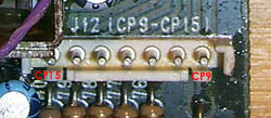
When a TUNE button is pressed for the first time on the transceiver connected to AH-3, Q1 sets the pin 13 of IC 7 high (+ 5V) allowing IC1 to start the clock and execute the program stored in ROM. At the same time Q2 is enabled, which powers up Vdd (pin 26 of IC1). The serial data (command) from the radio is read by IC1 via the buffer IC8. IC1 sends a KEY command to the transceiver through buffer stages of Q3 and Q4. The transceiver sets a low power TX level and keys up in CW mode. The tuner selects the TUNE path. Relays RL1 and RL2 are enabled and CP17 goes low (0.8 V) and the tuners searches for the match, dekeys the transceiver and send an appropriate message to the transceiver. If successful (i.e. match found), IC1 sends a READY message. If unsuccessful, the tuner returns to the default state. At the end of program execution IC1 sets pin 24 high which resets IC7 flip-flop. Pin 13 of IC7 returns to low, halting IC1. A subsequent TUNE command "wakes up" IC1 again. The software checks for the TUNE status in RAM. If the status was ON, it turns it OFF and goes to the bypass configuration (same as default) and enters the sleep mode. If the status was OFF, it attempts to tune the load again. While searching for the match, the IC 1 polls the analog circuitry for the SWR, phase and impedance information. The steady states may be probed at J12:
** measured on author's unit In addition to the above signals, IC 1 monitors the RF power level status (PWR) at the cathode of D4 connected to pin 7 of IC14. This signal is routed to pin 1 of IC1 through the IC13 buffer. Based on my notes, when the transceiver keys up in response to the tuner (after initiating the TUNE procedure), only a short pulse will be present on PWR line. IC1 expects it at the very beginning of tuning. If the pulse is not present, IC1 assumes there is no RF power connected to the tuner and terminates the operation. The transceiver is dekeyed and the TUNE flag is off (i.e. red LED in TUNE button on IC-706xxx). The relays are set to the default state. If the transceiver malfunctions and provides excessive power during tuning, the PWR line remains in the high state. IC1 detects this condition and dekeys the transceiver immediately in order to protect the tuner's RF circuitry. Uploaded on 29 Dec, 2000 | ||||||||||||||||||||||||||||||||