Diode Probe
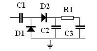
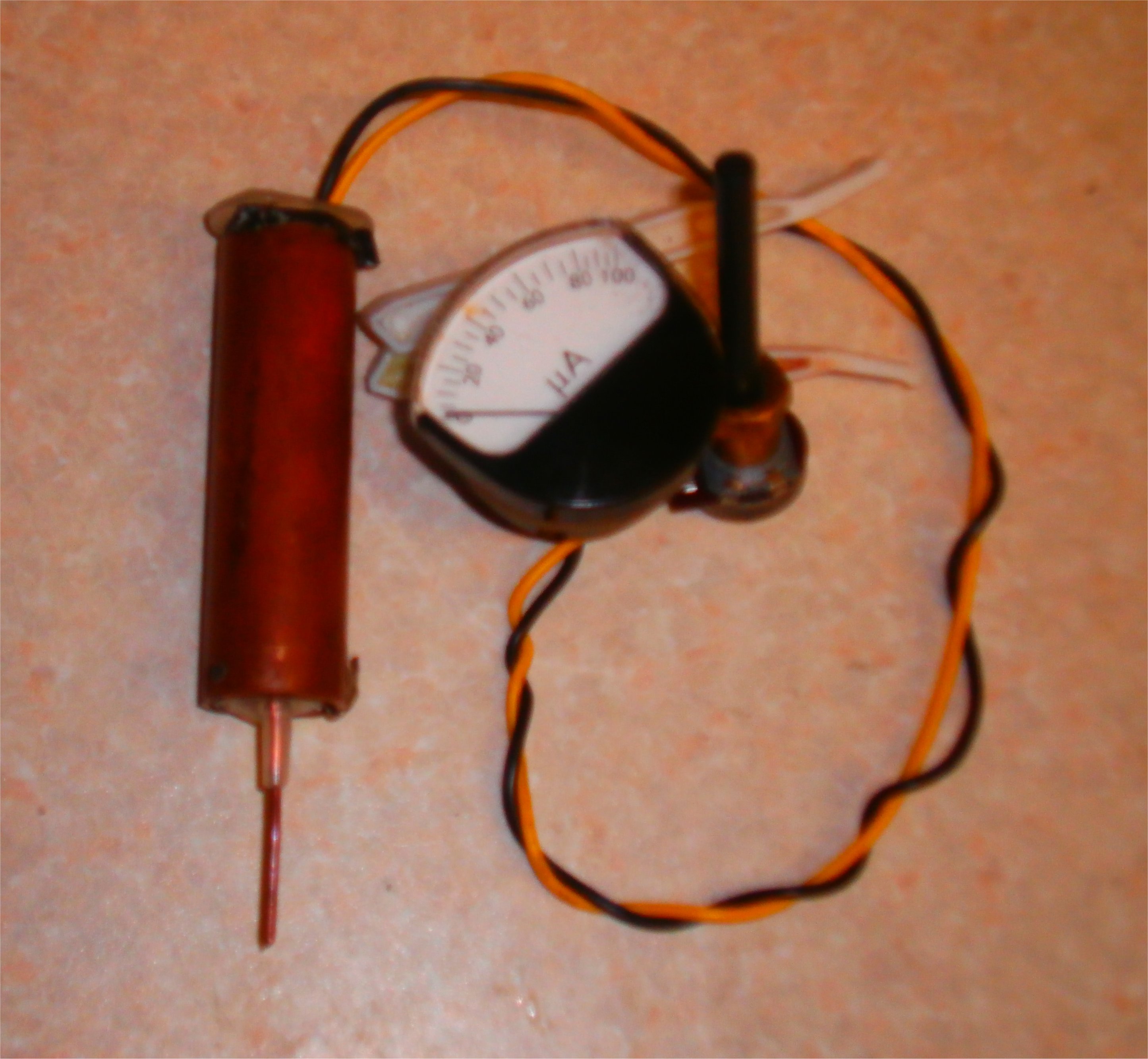
The diode probe is used to detect low levels of RF voltage in a circuit. From the diagram below the input is coupled with capacitor c1. Diodes d1, d2 rectify (voltage doubler circuit ) The rf is converted into a dc value with a ripple voltage . C2 smoothes the hf ripple from the diodes R1 and C3 and acts like a low pass filter. The choice of the value C3 is important to determine which type of output you require. If C3 is a large (10 uf ) value this will remove the ripple from the waveform giving a DC value output . If the RF signal you are trying to detect is amptitude modulated then make the value of c3 0.27uf This gives a dc output directly in proportion to rf amptitude and also gives an audio output as well. By adding a series capacitor (10u f to block the dc and let the ac through) couple this into the audio amplifier where you will hear the audio output. I put the dipole probe into a syringe and made c3 a fixed value of 0.27uf. If you just want a dc output add an external capacitor of 10uf across the c3. Also note that if you use a high impedance voltmeter across c3 and c3a this will charge up to 2.828 * peek rf voltage. The capacitor c3 and c3a will take a long time to discharge as capacitors are discharged through your high impedance voltmeter (time to discharge t (sec) =(1.4*R*C) R is impedance ofvolt meter ( typical impedance for high impedance voltmeter 10M ohms) .
And C =10uf then t=(1.4*10*10^6*10*10^-6)=140 sec. If you add a 10k across the value c3 and c3a this will reduce the 0.14sec.

R1 1K Ohms 1/8 w
C1 0.001uf Ceramic capacitor
C2 0.001uf Ceramic capacitor
C3 10uf electrolytic note the + goes R1 If you want am on signal make 0.27uf
D1 OA91 Germanium diodes or BAT46 Schottky diodes
I made the circuit board to fit the syringe. Keep the lead length to minimum as this will increase the frequency range and detect rf voltages. This is the layout I used.

Remove the plunger from the syringe and put this to one side then remove the needle and throw it a way. Make sure that it is correctly disposed of. The needles are very sharp and can hurt you so be careful with it Now make a hole in the side of the syringe as shown in diagram.
Push a thick piece of wire in the hole where needle was, ensure wire is pushed right through to the plunger end. Push a thin piece of wire through the small hole on the side, ensuring wire is pushed right though to plunger end. Solder wires on to the board, make sure thin wire is connected to the earth on the board, and the thick wire is connected to C1 on the board. The connect two insulated wires to the output on the board which is across C3. Now gently pull thick and thin wire in the syringe so the board slides inside the syringe. Make hole inside plunger and slide output wires through the hole exiting at the plunger .Tie knot to stop wires being pulled out, put plunger back into syringe use glue gun or wax to permanently fix plunger in place. I used 22mm copper pipe fixed over syringe as a RF shield and earth point. Tape may be necessary to adjust diameter of syringe for a tight fit. Then solder earth wire to copper tube. Fix jubilee clip around copper pipe, fit insulated piece of wire under jubilee clip, fit a croc clip to the end of the wire.
